| INTRO | PARTS |
SETS Moubal Jumbo |
MANUALS Moubal Jumbo |
MARKETING |
PRICE LISTS |
BUILDING |
MOUBAL RELATED |
| |
||||||||
|
 All cardboard parts are numbered Columns come in many lengths   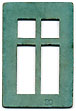 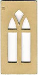 Wall panels are 1-1/8", 1-3/4", 2-1/4", 2-7/8" or 4 inches tall Connector strips are 1 inch wide Roof purlins are 3/4 inches wide  Roof panels come in many shapes and interlock at the ridge 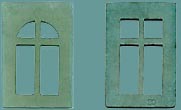 Around 1930, round upper windows were changed to square |
This page shows all the standard Mobaco and Jumbo parts, as well as the specialty parts for the Garage sets, the Wind Mill sets, and the never produced Set Z, as well as a few custom parts used in display models and illustrations. Towards the bottom is a section on the manufacturing of Mobaco parts and boxes. PART NUMBERING Most Mobaco cardboard parts are stamped with a part number. Stampings vary in location, in typeface and in font size. Instructions refer to these part numbers, making assembly easy. SIZES Interestingly, parts measurements are based on the imperial system (inches), not metric! In general: • Columns are 1/2" square, and spaced 2-1/4" on center, leaving 1-3/4" between them. They come in various lengths. • Wall panels are 2" wide, fitting into 1/8" deep grooves in the columns, leaving 1-3/4" exposed. • Stories are 4" tall, and wall panels are either 1-1/8", 1-3/4", 2-1/4", 2-7/8" or 4" tall. • Connector strips are 1" wide. • Sloping roofs are generally 45 degrees. Roof panels are supported by 3/4"-wide purlins of various lengths, which are inserted in slots in gable wall panels. Ridges are either centered between two rows of columns, or centered over a row of columns. Roof panels interlock at the ridge and are held in place by gravity. HISTORY Most parts remained unchanged through Mobaco's 40 year history. However, the windows (part 20) originally had a round top, and later were changed to square. This probably happened in 1931. The presence of round or square windows helps to date sets. The other item that changed are the columns. Until approximately 1950, columns were 1/2 inch square = 12.7 x 12.7 mm. Starting with the Jumbo ABCDE series, columns shrunk to 12 x 12 mm, and the holes in the floor plates shrunk accordingly. Old columns won't fit in the new floor plates (unless you jam them in). Originally, the cardboard parts were dark gray, light purplish red, light green and off-white. In 1931 the green and red become much brighter, at the same time the square window was introduced. Parts 60 and 62 initially were not numbered, but starting in 1931 the were finally numbered. This also helps to date sets. Yellow parts were introduced in some of the pre-war specialty sets, and used more by Jumbo after the war. According to Halbertsma, older parts were made from a dark cardboard core with colored face layers, later the color became integral. During the war, some parts were painted white cardboard. Click here for the part contents of the various sets. PARTS LIST Below a listing of parts that I found so far. Numbers correspond to the imprint on the parts. In some cases, parts have no imprint, but number is shown in a list of box contents or in a price list. This is noted in the table. Moubal and Jumbo were not very consistent with parts numbering. Duplicate numbers are shown in red. Jumbo introduced a few new parts, and dropped some of the original Moubal parts. See 3rd and 4th columns: • X's in the Moubal column are based on a Moubal price list dated August 1st, 1935. • X's in the Jumbo column are based on an August 1953 Jumbo illustrated parts list. Several parts are shown in this list, but strangely were not included in their sets. They are marked with (#) in the table. All images are at exact half size, except for a few very large items which are at quarter size. Unless otherwise noted, images are scans from my grandfather's (well-played) set. Note that Descriptions are my own, as I don't know of any official descriptions. All dimensions are approximate. I found there may be as much as 1/16" variation between identical parts. Certain parts were specific to special sets: the Garage Sets and the Windmill Sets. They are tabulated separately below. In 1931, Moubal proposed Set Z with a handful of new parts, as shown in the first Gnomes handbook. They were never put into production but were modeled in CAD by Koos Welling. |
| ALL PARTS |
|
|
|
|
|
|
||||||||||||||||||||||||||||||||||||||||
|
|
Column - guardrail height 1/2" x 1/2" x 1-3/4" (verify) long Number imprinted on older parts |
|
|
|
||||||||||||||||||||||||||||||||||||||||
|
|
Column - 2/3rd story high 1/2" x 1/2" x 3-1/8" long Number not imprinted on part |
|
|
|||||||||||||||||||||||||||||||||||||||||
|
|
Column - 1 story high 1/2" x 1/2" x 5-3/4" long Number imprinted on older parts |
|
|
|
||||||||||||||||||||||||||||||||||||||||
|
|
Column - 2 stories high 1/2" x 1/2" x 9-7/8" long Number imprinted on older parts |
|
|
|
||||||||||||||||||||||||||||||||||||||||
|
|
Column - 2-1/2 stories high 1/2" x 1/2" x 12" long Number imprinted on older parts |
|
|
|
||||||||||||||||||||||||||||||||||||||||
|
|
Column - 3 stories high 1/2" x 1/2" x 14-3/16" long Number imprinted on older parts |
|
|
|
||||||||||||||||||||||||||||||||||||||||
|
|
Column - 3-1/2 stories high 1/2" x 1/2" x 16-1/8" (410 mm) long Number not imprinted on part |
|
|
Shown at half the size of the other parts |
||||||||||||||||||||||||||||||||||||||||
|
|
Column - 4 stories high 1/2" x 1/2" x 18-1/8" (460 mm) long Number not imprinted on part |
|
|
Shown at half the size of the other parts |
||||||||||||||||||||||||||||||||||||||||
|
|
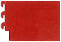
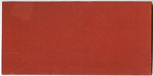
Solid wall panel, red 2" wide x 4" tall |
|
|
 |
||||||||||||||||||||||||||||||||||||||||
|
|
Solid wall panel, white 2" wide x 4" tall |
|
|
 |
||||||||||||||||||||||||||||||||||||||||
|
|
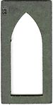
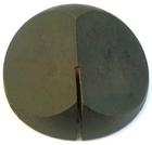
Peaked (Gothic) door panel, gray 2" wide x 4" tall |
|
|
 |
||||||||||||||||||||||||||||||||||||||||
|
|
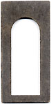
Arched door panel, gray 2" wide x 4" tall |
|
|
 |
||||||||||||||||||||||||||||||||||||||||
| 14 | Arched door panel,
yellow 2" wide x 4" tall |
|
 |
|||||||||||||||||||||||||||||||||||||||||
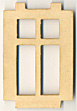
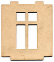
| 14 | Door panel with
rectangular openings,
gray 2" wide x 4" tall |
? |
? |
 |
||||||||||||||||||||||||||||||||||||||||
|
|
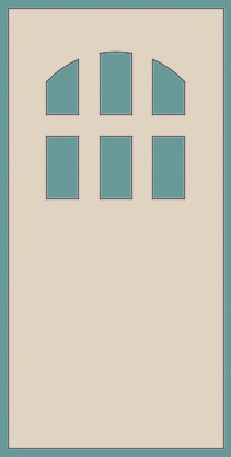
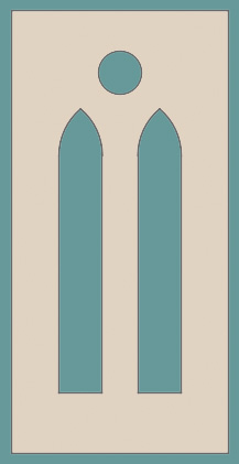
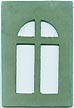
Peaked (Gothic) window panel, white 2" wide x 4" tall |
|
|
|
||||||||||||||||||||||||||||||||||||||||
|
|
Peaked (Gothic) window panel, yellow 2" wide x 4" tall |
|
 |
|||||||||||||||||||||||||||||||||||||||||
|
|
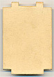
Solid wall panel, white 2" wide x 2-7/8" tall |
|
 |
|||||||||||||||||||||||||||||||||||||||||
|
|
Short square window panel with center
mullion, yellow 2" wide x 2-1/4" tall |
|
|
|||||||||||||||||||||||||||||||||||||||||
|
|
Short square window
panel with center mullion, white 2" wide x 2-1/4" tall |
|
X
|
 |
||||||||||||||||||||||||||||||||||||||||
|
|
Arched window panel with center mullion,
green 2" wide x 2-7/8" tall |
|
 |
|||||||||||||||||||||||||||||||||||||||||
|
|
Square window panel with center mullion,
green 2" wide x 2-7/8" tall |
|
|
|
||||||||||||||||||||||||||||||||||||||||
| 20 |
Square window
panel with center mullion, yellow
2" wide x 2-7/8"
tall
|
X | 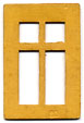 |
|||||||||||||||||||||||||||||||||||||||||
|
|
Solid wall panel, white 2" wide x 1-3/4" tall |
|
|
|
||||||||||||||||||||||||||||||||||||||||
|
|
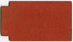
Solid wall panel, red 2" wide x 1-1/8" tall |
|
|
|
||||||||||||||||||||||||||||||||||||||||
|
|
Solid wall panel, white 2" wide x 1-1/8" tall Note: sometimes part 23 has a clock imprinted, but that is oficially Part 73 |
|
|
|
||||||||||||||||||||||||||||||||||||||||
|
|
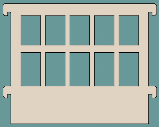
Slotted wall panel, green 2" wide x 1-1/8" tall |
|
|
|
||||||||||||||||||||||||||||||||||||||||
|
|
Slotted wall panel, yellow 2" wide x 1-1/8" tall Moubal only used yellow it in their Garage Sets |
|
|
|||||||||||||||||||||||||||||||||||||||||
|
|
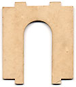
Arched wall panel, green 2" wide x 1-1/8" tall |
|
|
|
||||||||||||||||||||||||||||||||||||||||
|
|
Crenelated wall panel, gray 2" wide x 5/8" tall (verify) |
|
X
|
|
||||||||||||||||||||||||||||||||||||||||
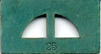
| 26 | Crenelated wall panel, gray 2" wide x 7/8" tall |
|
X | |||||||||||||||||||||||||||||||||||||||||
|
|
Solid wall panel, white 2" wide x 3/8" tall |
|
|
|
||||||||||||||||||||||||||||||||||||||||
|
|
Solid wall panel, white 2" wide x 13/16" tall |
|
|
|
||||||||||||||||||||||||||||||||||||||||
| 28H |
Solid wall panel, white 2" wide x 5/8" tall (verify) |
|
|
|||||||||||||||||||||||||||||||||||||||||
|
|
Tall clock panel, white with printed
clock 2" wide x 2-7/8" tall |
|
 |
|||||||||||||||||||||||||||||||||||||||||
|
|
Crenelated wall panel with gap (similar
to part 26) 2" wide x ...." tall (verify) |
|
|
|||||||||||||||||||||||||||||||||||||||||
|
|
Connector strip, 1-1/2 holes, gray 15/16" wide x ....." long Similar to 42, but with one hole open, similar to 55 |
|
||||||||||||||||||||||||||||||||||||||||||
|
|
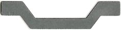
Connector strip, 1 hole + cantilever,
gray 15/16" wide x 2-3/16" long |
|
|
|
||||||||||||||||||||||||||||||||||||||||
|
|
Connector strip, 1 hole + two
cantilevers, gray 15/16" wide x 3-7/16" long |
|
|
|
||||||||||||||||||||||||||||||||||||||||
|
|
Connector strip, 2 holes, gray 15/16" wide x 3-3/16" long |
|
|
|
||||||||||||||||||||||||||||||||||||||||
|
|
Connector strip, 2 holes + one
cantilever, gray 15/16" wide x 4-7/16" long |
|
|
|||||||||||||||||||||||||||||||||||||||||
|
|
Connector strip, 2 holes + two
cantilevers, gray 15/16" wide x 5-11/16" long |
|
|
|
||||||||||||||||||||||||||||||||||||||||
|
|
Connector strip, 3 holes, gray 15/16" wide x 5-7/16" long |
|
|
|
||||||||||||||||||||||||||||||||||||||||
|
|
Connector strip, 3 holes + one
cantilever, gray 15/16" wide x 6-11/16" long |
|
|
|
||||||||||||||||||||||||||||||||||||||||
|
|
Connector strip, 3 holes + two
cantilevers, gray 15/16" wide x 8" long |
|
|
|
||||||||||||||||||||||||||||||||||||||||
|
|
Connector strip, 4 holes, gray 15/16" wide x 7-11/16" long |
|
|
|
||||||||||||||||||||||||||||||||||||||||
|
|
Connector strip, 4 holes + end, gray 15/16" wide x 9" long |
|
|
|||||||||||||||||||||||||||||||||||||||||
|
|
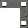
Corner connector strip, 3 holes 15/16" wide x 3-1/4" x 3-1/4" |
|
 |
|||||||||||||||||||||||||||||||||||||||||
|
|
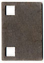
Corner connector strip, single hole 15/16" wide x 2-1/4" x 2-1/4" |
|
 |
|||||||||||||||||||||||||||||||||||||||||
|
|
Connector strip, 1 hole, gray 1" x 1" |
|
|
|||||||||||||||||||||||||||||||||||||||||
|
|
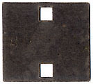
Connector strip, 2 holes, each with
slot, gray 15/16" wide x 3-3/16" long |
|
|
|||||||||||||||||||||||||||||||||||||||||
|
|
Half of arched door panel 2" wide x 2-1/4" tall |
|
|
 |
||||||||||||||||||||||||||||||||||||||||
|
|
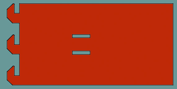
Floor panel, 2x 1-1/2 holes, gray 3-3/16" x 2-3/4" |
|
|
 |
||||||||||||||||||||||||||||||||||||||||
|
|
Floor panel, 2 holes, single cantilever,
gray 3-3/16" x 2-3/16" |
|
|
 |
||||||||||||||||||||||||||||||||||||||||
|
|
Floor panel, 2 holes, double cantilever,
gray 3-3/16" x 3-7/16" |
|
|
 |
||||||||||||||||||||||||||||||||||||||||
|
|
Floor panel, 4 holes, gray 3-3/16" x 3-3/16" |
|
|
 |
||||||||||||||||||||||||||||||||||||||||
|
|
Floor panel, 4 holes, single cantilever,
gray 3-3/16" x 4-7/16" |
|
|
 |
||||||||||||||||||||||||||||||||||||||||
|
|
Floor panel, 4 holes, double cantilever,
gray 3-3/16" x 5-5/8" |
|
|
 |
||||||||||||||||||||||||||||||||||||||||
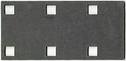
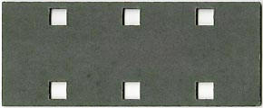
|
|
Floor panel, 6 holes, gray 3-3/16" x 5-7/16" |
|
|
 |
||||||||||||||||||||||||||||||||||||||||
|
|
Floor panel, 6 holes, single cantilever,
gray 3-3/16" x 6-11/16" |
|
 |
|||||||||||||||||||||||||||||||||||||||||
|
|
Floor panel, 6 holes, double cantilever,
gray 3-3/16" x 7-7/8" |
|
 |
|||||||||||||||||||||||||||||||||||||||||
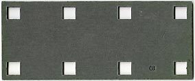
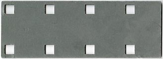
|
|
Floor panel, 8 holes, gray 3-3/16" x 7-11/16" |
|
|
 |
||||||||||||||||||||||||||||||||||||||||
|
|
Floor panel, 8 holes, single cantilever,
gray 3-3/16" x 8-15/16 |
|
 |
|||||||||||||||||||||||||||||||||||||||||
|
|
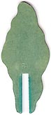
Short tree, green 1-7/8" wide x 2-3/8" tall |
|
 |
|||||||||||||||||||||||||||||||||||||||||
|
|
Tall tree, green 1-7/8" wide x 4-1/2" tall |
|
 |
|||||||||||||||||||||||||||||||||||||||||
|
|
Short clock panel, white, with printed
clock 2" wide x 1-1/8" tall Note: This part is sometimes shown as Part 23. |
|
|
|||||||||||||||||||||||||||||||||||||||||
| 74 |
Windmill
sail |
X |
 This item appears in Jumbo illustrated parts diagrams, but so far not a single example has been found |
|||||||||||||||||||||||||||||||||||||||||
| 75 |
Windmill
sail? 2" wide x 4" long (incl. point) |
X |
 |
|||||||||||||||||||||||||||||||||||||||||
|
|
Chimney 1/2" x 1/2" x 1" tall |
|
|
|||||||||||||||||||||||||||||||||||||||||
|
|
Purlin, 3-1/2 bays long, gray 3/4" wide x 8-5/8" long |
|
|
|
||||||||||||||||||||||||||||||||||||||||
|
|
Purlin, 3 bays long, gray 3/4" wide x 7-1/2" long |
|
|
|
||||||||||||||||||||||||||||||||||||||||
|
|
Purlin, 2-1/2 bays long, gray 3/4" wide x 6-1/2" long |
|
|
|||||||||||||||||||||||||||||||||||||||||
|
|
Purlin, 2-1/2 bays long, with slot, gray
3/4" wide x 6-1/2" long Note: This part is shown in Jumbo's illustrated parts list without the slot (similar to part 82). |
|
|
|
||||||||||||||||||||||||||||||||||||||||
|
|
Purlin, 2 bays long, gray 3/4" wide x 5-1/2" long |
|
|
|
||||||||||||||||||||||||||||||||||||||||
|
|
Purlin, 1-1/2 bays long, gray 3/4" wide x 4-1/8" long |
|
|
|
||||||||||||||||||||||||||||||||||||||||
|
|
Purlin, 1 bay long, gray 3/4" wide x 3-1/8" long |
|
|
|
||||||||||||||||||||||||||||||||||||||||
|
|
Purlin, 1/2 bay long, gray 3/4" wide x 2" long |
|
|
|||||||||||||||||||||||||||||||||||||||||
|
|
Zigzag purlin, gray 6-1/2" wide x 1-1/2" tall Allows for purlins to cross. |
|
|
 |
||||||||||||||||||||||||||||||||||||||||
|
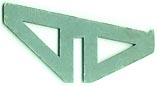
|
Cantilever truss, green 4-1/8" wide x 2-1/4" tall Top has 10 degree pitch, resulting is gently sloping roof. Notch prevents roof element from sliding off. |
|
|
 |
||||||||||||||||||||||||||||||||||||||||
|
|
Cantilever truss, gray 4-1/8" wide x 2-1/4" tall Top has 10 degree pitch, resulting is gently sloping roof |
 |
||||||||||||||||||||||||||||||||||||||||||
|
|
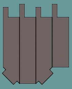
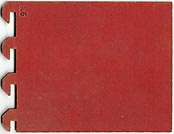
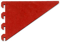
Long roof panel, 4 notches wide, red 3-5/8" wide x 7-1/16" tall |
|
|
|||||||||||||||||||||||||||||||||||||||||
|
|
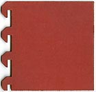
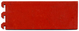
Medium roof panel, 4 notches wide, red 3-5/8" wide x 5-3/8" tall |
|
|
 |
||||||||||||||||||||||||||||||||||||||||
|
|
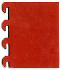
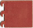
Medium roof panel, 4 notches wide with
corner notched, red 3-5/8" wide x 5-3/8" tall |
|
 |
|||||||||||||||||||||||||||||||||||||||||
|
|
Shorter roof panel, 4 notches wide, red
3-5/8" wide x 4-3/4" tall |
|
 |
|||||||||||||||||||||||||||||||||||||||||
|
|
Short roof panel, 4 notches wide, red 3-5/8" wide x 3-3/4" tall |
|
 |
|||||||||||||||||||||||||||||||||||||||||
|
|
Short roof panel, 4 notches wide, red 3-5/8" wide x 3-1/8" tall |
|
|
 |
||||||||||||||||||||||||||||||||||||||||
|
|
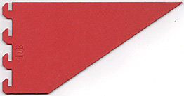
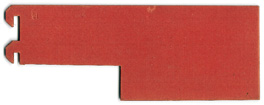
Trapezoidal roof panel, 4 notches wide,
red 3-5/8" wide x 7" tall |
|
 |
|||||||||||||||||||||||||||||||||||||||||
|
|
Trapezoidal roof panel, 4 notches wide,
mirrored notches, red 3-5/8" wide x 7" tall |
|
 |
|||||||||||||||||||||||||||||||||||||||||
|
|
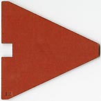
Triangular roof panel, 4 notches wide,
red 3-5/8" wide x 5-3/8" tall |
|
|
 |
||||||||||||||||||||||||||||||||||||||||
|
|
Triangular roof panel, 4 notches wide,
mirrored notches, red 3-5/8" wide x 5-3/8" tall |
|
|
 |
||||||||||||||||||||||||||||||||||||||||
|
|
Long roof panel, 3 notches wide, red 2-5/8" wide x 7-1/16" tall |
|
 |
|||||||||||||||||||||||||||||||||||||||||
|
|
Long roof panel, 3 notches wide, notched
along lower side, red 2-5/8" wide x 7-1/16" tall |
|
 |
|||||||||||||||||||||||||||||||||||||||||
|
|
Medium roof panel, 3 notches wide, red 2-5/8" wide x 5-3/8" tall |
|
|
 |
||||||||||||||||||||||||||||||||||||||||
|
|
Short roof panel, 3 notches wide, red 2-5/8" wide x 3-1/4" tall |
|
|
 |
||||||||||||||||||||||||||||||||||||||||
|
|
Long roof panel, 3 notches
wide, notched along upper side, red 2-5/8" wide x 7-1/16" tall |
|
|
|||||||||||||||||||||||||||||||||||||||||
|
|
Long roof panel, 2 notches wide, red 1-5/8" wide x 7-1/16" tall |
|
 |
|||||||||||||||||||||||||||||||||||||||||
|
|
Medium roof panel, 2 notches wide, red 1-5/8" wide x 5-1/4" tall |
|
 |
|||||||||||||||||||||||||||||||||||||||||
|
|
Short roof panel, 2 notches wide, red 1-5/8" wide x 3-1/8" tall |
|
|
 |
||||||||||||||||||||||||||||||||||||||||
|
|
Cantilever roof panel, 3 bays wide, red
6-5/8" x 2-15/16" |
|
 |
|||||||||||||||||||||||||||||||||||||||||
|
|
Cantilever roof panel, 2 bays wide, red
4-3/8" x 2-15/16" |
|
 |
|||||||||||||||||||||||||||||||||||||||||
|
|
Cantilever roof panel, 1 bay wide, red 2-1/8" x 2-15/16" |
|
 |
|||||||||||||||||||||||||||||||||||||||||
|
|
Flat roof panel, red 8-1/8" long x 4" wide Used in conjunction with part 89 |
|
|
 |
||||||||||||||||||||||||||||||||||||||||
|
|
Mansard/hip roof panel, middle, red 2-1/4" wide x 3-15/16" high |
|
 |
|||||||||||||||||||||||||||||||||||||||||
|
|
Mansard/hip roof panel, corner, red 2" wide x 3-7/8" high |
|
 |
|||||||||||||||||||||||||||||||||||||||||
|
|
Mansard/hip roof panel, peak, red 3-15/16" wide x 3-7/8" high |
|
 |
|||||||||||||||||||||||||||||||||||||||||
|
|
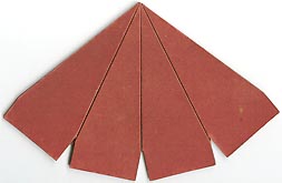
Steeple roof, red 1-3/4" wide at base of each section x 4-7/16" tall Overall part size: 6-7/8" wide x 4-1/2" tall Part has three folds allowing it to bend into a tall pyramid with a square base |
|
|
 |
||||||||||||||||||||||||||||||||||||||||
|
|
Cap for steeple roof, brass(?), painted
red 7/8" wide at base, 1-3/8" tall to peak, 2-3/4" tall to top of ring Fits on Part 160. |
|
 |
|||||||||||||||||||||||||||||||||||||||||
|
|
Narrow roof strip, long, red appr. 5/8" x 7-1/4" |
|
|
|||||||||||||||||||||||||||||||||||||||||
|
|
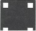
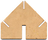
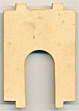
Peaked gable wall panel, centered
between columns, white 2" wide x 1-3/4" tall |
|
|
 |
||||||||||||||||||||||||||||||||||||||||
|
|
Sloping gable wall panel, 1 bay wide,
white 2" wide x 3-7/16" tall |
|
 |
|||||||||||||||||||||||||||||||||||||||||
|
|
Peaked gable wall panel, 2 bays wide,
white 4-1/4" wide x 3-1/2" tall |
|
|
 |
||||||||||||||||||||||||||||||||||||||||
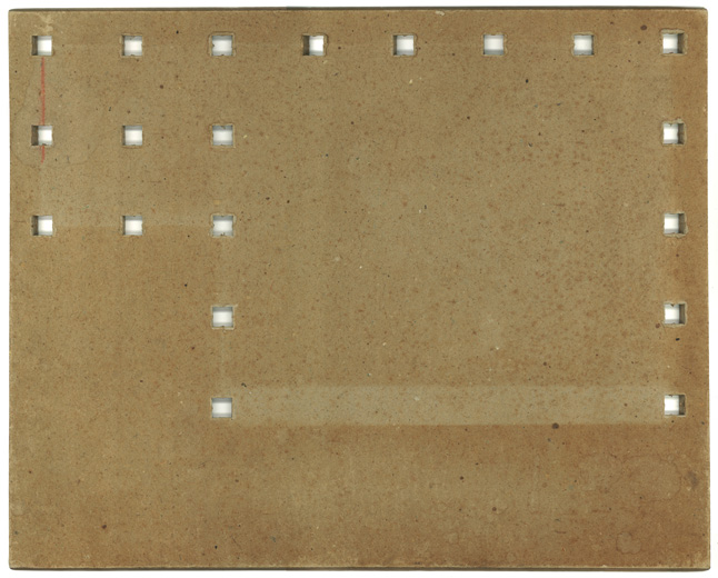
Floor plates went through several changes. Initially, they were made from cardboard layers glued together, and later they were made from hardboard. So far, this is what I was able to make of their history (changes in design are highlighted in yellow):
|
||||||||||||||||||||||||||||||||||||||||||||
|
|
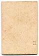
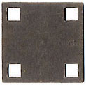
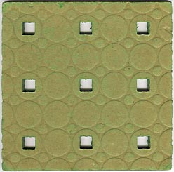
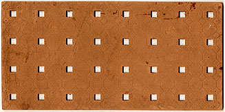
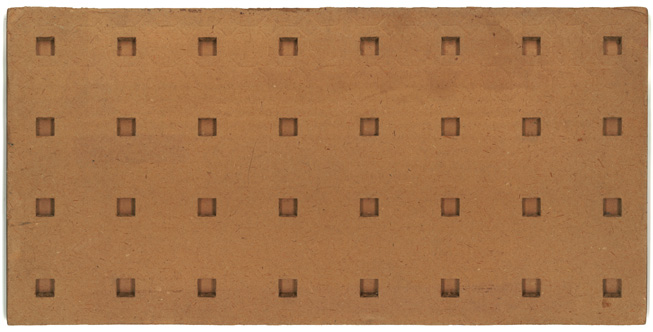
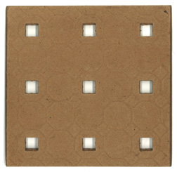
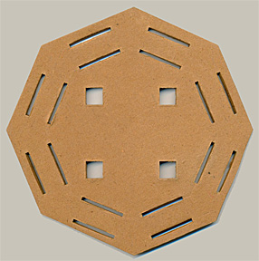
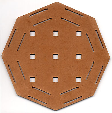
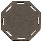
Floor Plate, 2 holes x 2 holes, brown 4" x 4" x 1/4" thick Number not imprinted on part Note: other side has no tile pattern |
|
|
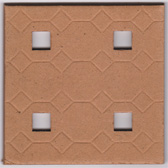 
Octogonal pattern (Moubal)
Circle pattern (Jumbo)
|
||||||||||||||||||||||||||||||||||||||||
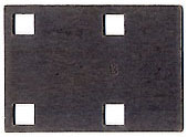
| 200 |
Floor Plate, 2
holes x 2 holes, tan 4" x 4" x 1/4" thick Number not imprinted on part Note: other side has no tile pattern |
X |
 Circle pattern (Jumbo) |
|||||||||||||||||||||||||||||||||||||||||
|
|
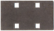
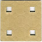
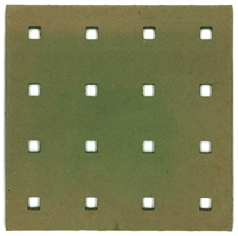
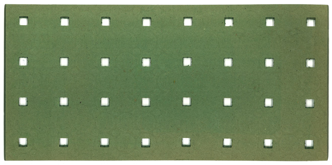
Floor Plate, 2 holes x 2 holes, green
4-1/2" x 4-1/2" x 1/4" thick Note that this plate is 1/2" larger than the one above! Number not imprinted on part Note: other side has no tile pattern |
|
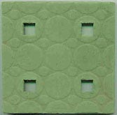 Circle pattern (Jumbo) |
|||||||||||||||||||||||||||||||||||||||||
|
|
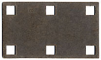
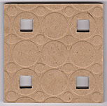
Floor Plate, 3 holes x 3 holes, brown 6-5/8" x 6-5/8" x 1/4" thick Moubal version has column supports at the bottom. These were produced around 1925-1926. Jumbo version never had column supports. Moubal version with open holes is Part 204 Number not imprinted on part Note: other side has no tile pattern |
|
|
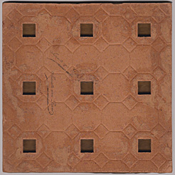 
Octogonal pattern
(Moubal)
Circle pattern (Jumbo)
|
||||||||||||||||||||||||||||||||||||||||
| 201 |
Floor Plate, 3
holes x 3 holes, tan 6-5/8" x 6-5/8" x 1/4" thick Number not imprinted on part Note: other side has no tile pattern |
X |
 Circle pattern (Jumbo) |
|||||||||||||||||||||||||||||||||||||||||
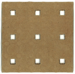
|
|
Floor Plate, 3 holes x 3 holes, green 6-5/8" x 6-5/8" x 1/4" thick Number not imprinted on part Note: other side has no tile pattern |
|
 Circle pattern (Jumbo) |
|||||||||||||||||||||||||||||||||||||||||
|
|
Floor Plate, 4 holes x 4 holes, brown
8-7/8" x 8-7/8" x 1/4" thick Number not imprinted on part. Other side generally has no tile pattern (although there are examples with tile pattern on both sides) |
|
|
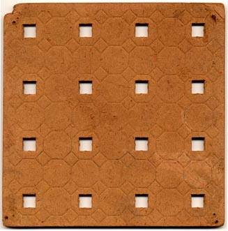 Octagonal pattern (Moubal) |
||||||||||||||||||||||||||||||||||||||||
| 202 |
Floor
Plate, 4 holes x 4 holes, brown, with column supports 8-7/8" x 8-7/8" x 1/4" thick Number not imprinted on part. Other side has no tile pattern |
X | 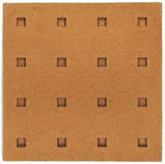 Octagonal pattern (Moubal) |
|||||||||||||||||||||||||||||||||||||||||
|
|
Floor Plate, 4 holes x 4 holes, green
8-7/8" x 8-7/8" x 1/4" thick |
|
 No pattern, probably misprint (Jumbo) |
|||||||||||||||||||||||||||||||||||||||||
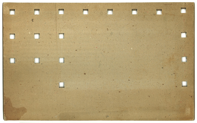
|
|
Floor Plate, 4 holes x 8 holes, brown
8-7/8" x 17-7/8" x 1/4" thick Number not imprinted on part. Other side has no tile pattern |
|
|
 Octagonal pattern (Moubal) 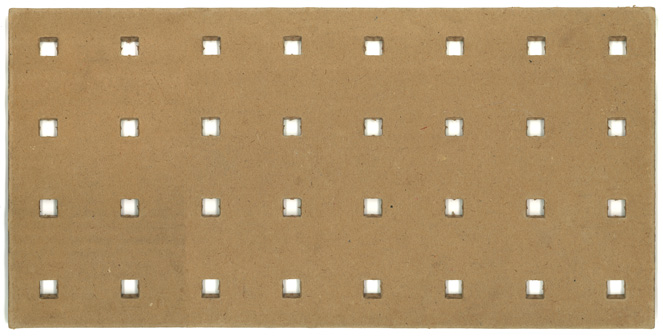 No pattern, probably misprint (Jumbo) Shown at half the size of the other parts |
||||||||||||||||||||||||||||||||||||||||
| 203 |
Floor Plate, 4
holes x 8 holes, brown, with column supports
8-7/8" x 17-7/8" x 1/4" thick Number not imprinted on part. Other side has no tile pattern |
X |
 Octagonal pattern (Moubal) Shown at half the size of the other parts |
|||||||||||||||||||||||||||||||||||||||||
| 203 |
Floor Plate, 4
holes x 8 holes, tan 8-7/8" x 17-7/8" x 1/4" thick Number not imprinted on part. Other side has no tile pattern |
X? |
Looking for scan |
|||||||||||||||||||||||||||||||||||||||||
|
|
Floor Plate, 4 holes x 8 holes, green
8-7/8" x 17-7/8" x 1/4" thick Number not imprinted on part. Other side has no tile pattern |
|
 Circle pattern (Jumbo) Shown at half the size of the other parts |
|||||||||||||||||||||||||||||||||||||||||
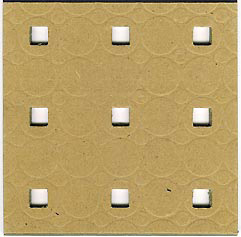
| 204 |
Floor
Plate, 3 holes x 3 holes, brown 6-5/8" x 6-5/8" x 1/4" thick Similar to Moubal part 201 except with open holes Number not imprinted on part Note: other side has no tile pattern |
X |
 |
|||||||||||||||||||||||||||||||||||||||||
|
Scans for
parts 1, 13, 15, 19, 23, 26 (Moubal & Jumbo),
27, 50 ,51, 52, 53, 54, 55, 66, 67, 68, 69, 70,
71, 73, 76, 81, 87, 88, 105, 106, 108, 124, 143,
Special parts for Garage Sets No. 1 and No. 2, and Small Garage See general parts list above for
standard parts |
|
|
|
|
|
|
One-story column with mitered top and
hole for spring (part 162). This column is the same for Garage No. 1 and No. 2. 1/2" x 1/2" x 5-5/8" (143 mm) long. Angle of cut is appr. 17.5º Number not imprinted on part |
|
| 2A | One-story column
with nail and hole for curtain rod, for Small Garage. 1/2" x 1/2" x appr. 5-3/4" (145 mm) long Number not imprinted on part |
|
|
|
Short column with mitered bottom and
hole for spring (part 162), for Garage No. 1 1/2" x 1/2" x 2-1/2" (64 mm) long. Angle of cut is appr. 17.5º Number not imprinted on part |
|
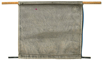
| 3A | Gray curtain with
wood dowel and steel weight, for Small Garage Curtain: 6" (151 mm) x 5-3/8" (137 mm) Wood dowel: 9-1/4" (235 mm) x 7/32" (5.5 mm) diameter. Number not imprinted on part |
 |
|
|
Sliding door track - lower 1" wide x 11-1/8" long Number not imprinted on part Works with part 72 (see below) |
|
|
|
Short column with angled bottom (miter)
and hole for spring (part 162), for Garage No. 2 1/2" x 1/2" x 3-5/8" (93 mm) long. Angle of cut is appr. 17.5º Number not imprinted on part |
|
|
|
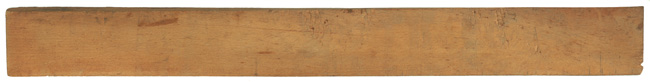
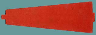
Tapered ramp, wood - fits next to ground
plate 1-7/8" (45 mm) wide x 17-3/4" (450 mm) long x 1/4" (6 mm) thick |
 |
|
|
Arched door panel, yellow 2" wide x 4" tall |
|
|
|
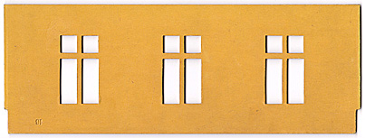
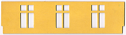
Sloping wall panel with windows, tall,
for Garage No. 2, yellow appr. 11" (279 mm) wide x 4" (101 mm) tall Used in conjunction with part 183 |
|
|
|
Sloping wall panel with windows, short,
for Garage No. 1, yellow appr. 11" (279 mm) wide x appr. 3" (74 mm) tall Used in conjunction with part 184 |
|
|
|
Arched or square window panel with
center mullion, yellow 2" wide x 2-7/8" tall |
|
|
|
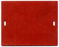
Slotted wall panel, yellow 2" wide x 1-1/8" tall |
|
|
|
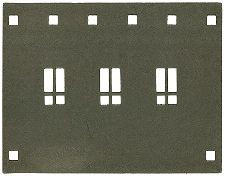
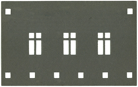
Roof panel with skylights, gray, for
Garage No. 2 9-3/4" x 13-1/2" The holes for the posts are rectangular, to accommodate the angle of the roof panel relative to the posts. The "skylights" are identical to the cut-outs of window panels. The later Jumbo short tree has the same part number. |
 |
| 70 | Roof panel with fold,
gray, for Small Garage 8" (205 mm)" x 2-5/8" (66 mm) + 8" (205 mm) x 5-11/16" (145 mm) The holes for the posts are
rectangular, to accommodate the angle of the roof
panel relative to the posts. The earlier Roof for Garage No. 2 and the later Jumbo short tree have the same part number. |
 |
|
|
Floor panel, 3 holes, single cantilever,
gray 2-3/16" x 5-7/16" |
 |
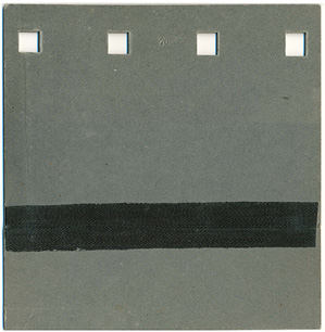
| 71 | Low-slope gable end
panel, 2.4 bays, white, for Small Garage 2-5/8" (68 mm) wide x 1-1/8" (28 mm) tall Slopes are appr. 60º and 23.5º |
 |
|
|
Sliding door track - upper track 1" wide x 12-1/4" long Number not imprinted on part Note: Wood track is glued to cardboard strip with column holes. Shown is the under side. Upper side is cardboard |
|
|
|
Roof panel with skylights, gray, for
Garage No. 1 (similar to Part 70) 13-1/2" (320 mm) x 7-7/8" (200 mm) Note that the holes for the posts are rectangular, to accommodate the angle of the roof panel relative to the posts. The "skylights" are identical to the cut-outs of window panels. The later Jumbo short clock panel has the same part number |
 |
|
|
Sliding Garage Door 4-5/16" wide x 5-1/2" tall |
 |
|
|
Spring to connect the mitered columns at
the plate height. Also exists as bent brass rod |
not to scale
double size
|
|
|
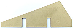
Low-slope gable end panel, 4 bays,
white, for Garage No. 2 8-11/16" wide x 3-5/16" tall Slopes are appr. 22.5º and 58.5º |
 |
|
|
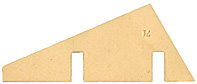
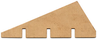
Low-slope gable end panel, 3 bays,
white, for Garage No. 1 6-7/16" wide x 2-1/2" tall Slopes are appr. 20.5º and 57.5º |
|
|
|
Garage floor plate for Garage No. 2 appr. 14" x 17-1/2" x 1/4" thick. Officially 450 x 360 mm (see 1935 Leaflet) Number not imprinted on part |
 |
|
|
Garage floor plate for Garage No. 1 appr. 8-7/8" x 17-1/2" x 1/4" thick. Officially 450 x 280 mm (see 1935 Leaflet) Number not imprinted on part |
 |
| PARTS USED IN BOTH WINDMILL NO. 1
AND WINDMILL NO. 2 |
||
|
|
Description | Image |
| - |
Brass clip 5/8" x 5/8" x yyy" high Installed between the two wooden sail posts to keep them perpendicular to each other |
|
| - |
Brass sleeve yyy" diameter x yyy" long The sleeve passes through holes in the sail posts |
|
| - |
Brass washer yyy" diameter Goes between the sleeve and the roof cap |
|
| - |
Brass screw 1-1/4" long x 1/8" diameter |
|
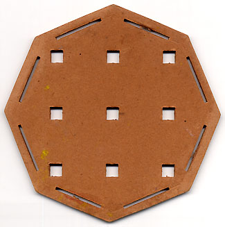
| SPECIAL PARTS FOR WINDMILL SET
NO. 1 AND NO. 2 Parts are shown at the same scale |
|||
| no. | Description | WINDMILL
NO. 1 |
WINDMILL
NO. 2 |
| - |
Ground Floor plate,
tan Number not imprinted on part Quantity: 1 |
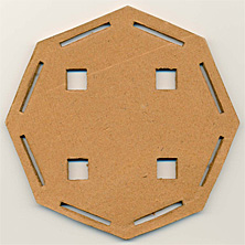 5-1/2" x 5-1/2" octagonal x 1/4" thick |
 8" x 8" octagonal x 1/4" thick |
| - |
Second Floor plate, tan Number not imprinted on part Quantity: 1 |
 7" x 7" octagonal x 1/4" thick |
 9-3/4" x 9-3/4" octagonal x 1/4" thick |
| - |
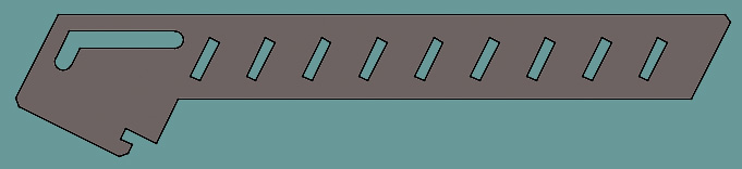
Guardrails
panel, green Number not imprinted on part Quantity: 8 |
2-9/16" long x 9/16" high |
3-3/4" long x 11/16" high |
| - |
Wall panel, solid,
white Number not imprinted on part Quantity: 3 |
 2" wide x 2-7/8" high |
 2-7/8" wide x 3-5/16" high |
| - |
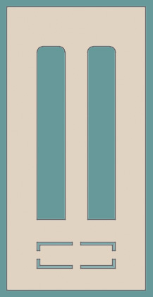
Wall panel, with
window, white Number not imprinted on part Quantity: 3 |
 2" wide x 2-7/8" high |
 2-7/8" wide x 3-5/16" high |
| - |
Wall panel, with
arched door opening, white Number not imprinted on part Quantity: 2 |
 2" wide x 2-7/8" high |
 2-7/8" wide x 3-5/16" high |
| - |
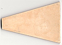
Spire wall panel A,
red Number not imprinted on part Quantity: 4 |
 2" at base & 3/4" at apex x 6" tall |
 2-7/8" at base & 1-3/8" at apex x 8-1/2" tall |
| - |
Spire wall panell
B, red Number not imprinted on part Quantity: 4 |
 2" at base & 3/4" at apex x 6" tall |
 2-7/8" at base & 1-3/8" at apex x 8-1/2" tall |
| - |
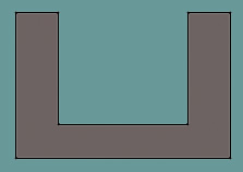
Flat roof panel,
top of spire, gray Number not imprinted on part Quantity: 1 |
 2-1/2" x 2-1/2" (between sides) |
 3-5/8" x 3'5/8" (between sides) |
| - |
Wooden roof cap
(roof of windmill), black Quantity: 1 |
 2-3/8" diameter x yyy" high |
 3-3/4" (95 mm) diameter x 1-7/8" (47 mm) high |
| - | Wooden sail beam
(spokes). Has a groove in each side to insert a sail. Quantity: 2 |
11-1/8" long x 1/2" wide x yyy" thick |
15-3/4" long x 1/2" wide x yyy" thick |
| - |
Sails, white Quantity: 4 |
 4-3/4" long x 1" at narrow side x 1-3/8" at wide side |
 7-1/8" long x 1" at narrow side x 1-5/8" at wide side |
|
-
|
Tail
piece, white Quantity: 1 |
 2-3/8" long x 5/16" at narrow side x 1-1/2" at wide side |
 3-1/4" long x 5/8" at narrow side x 2-3/8" at wide side |
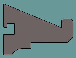
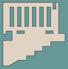
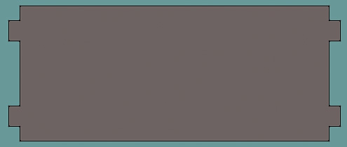
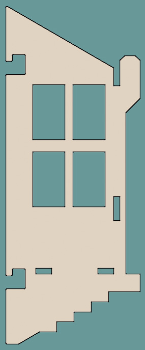
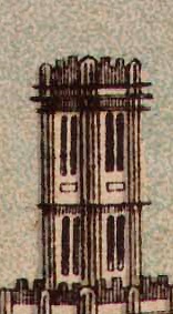
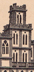
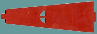
Special Parts for Set Z In 1931, Moubal announced the issuance of Set Z with a number of new parts, specifically a chimney, a stairway, a conservatory, a balcony, a new entry door, a taller gate, a canopy and a flag pole. However, nor Set Z, nor these parts were ever introduced. Except that the flagpole (part no. 161) was already part of Sets 2a, 3 and 4. In 2021, Koos Welling and I recreated these parts in CAD, basing the designs on these three illustrations (left to right): - a photo in a 1931 article by "Natuur en Techniek" - an illustration in the 1931 Gnomes manual - an illustration from a 1934 Mobaco letterhead 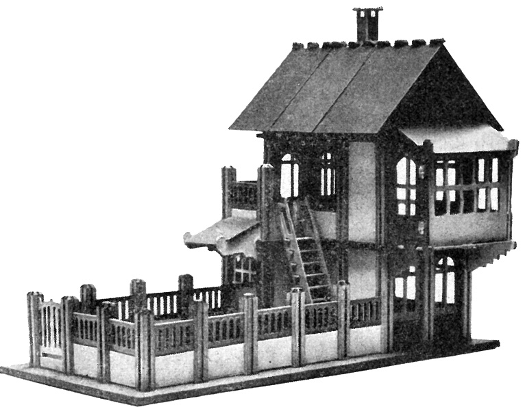  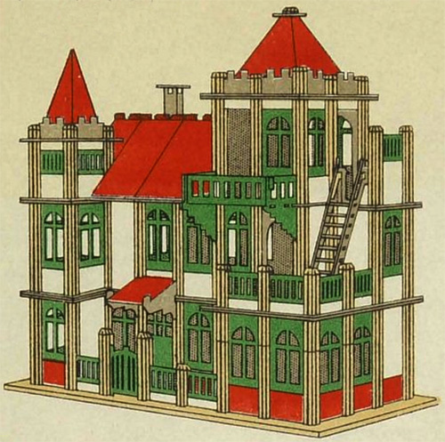 ...as well as on this home-made brass/aluminum prototype of the canopy, found by Barend Westerveld in a large Mobaco purchase: 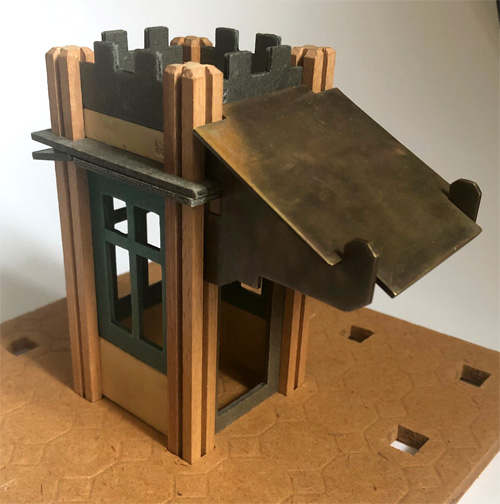
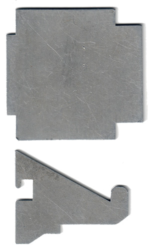 Photo and scan courtesy of Barend Westerveld I created a perspective reconstruction to evaluate sizes and angles of various parts. This showed that the Canopy roof has an angle of 22.5 degrees (half of 45º), the Bay Widow has a roof slope of 30 degrees and the Bay Window support bracket also has an angle of 30 degrees. The stairway has a 2:1 slope. The windows in the Bay Window have lower sills than regular windows, about the same height as the low wall panels (part #23): 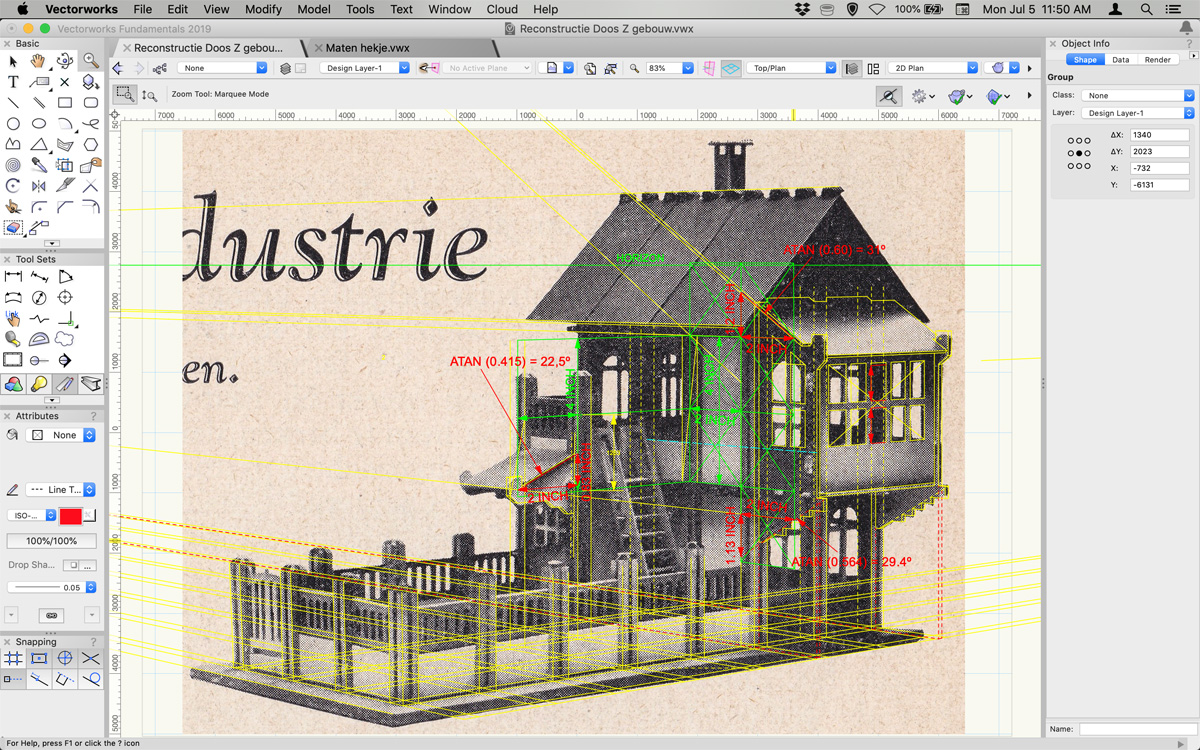 Here and there we had to guess as information was incomplete, filling in the gaps while remaining faithful to the Mobaco design language. Here the final result: 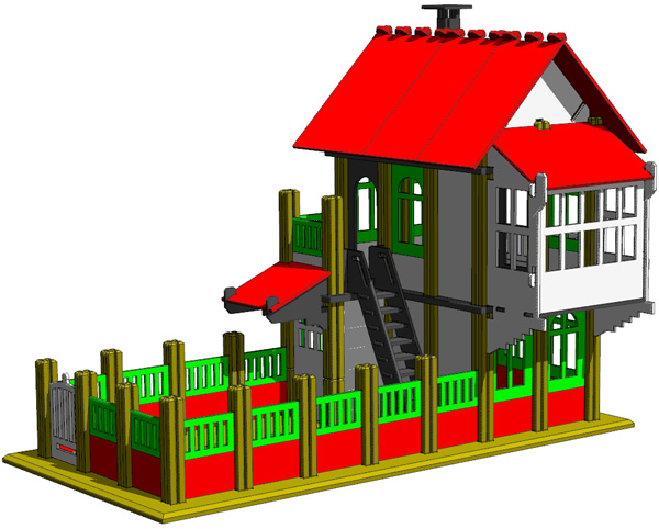 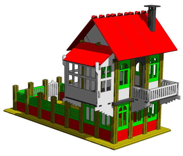 CAD drawings courtesy Koos Welling Koos made these animated GIFs of the three models that inspired this project: 
Animations courtesy of Koos Welling
Other Special Parts In some illustrations, special parts are shown that were never produced. Koos Welling drafted them.
|
||||||||||||||||||||||||||||||||||||||||||||||||||||||||||||||||||||||||||
MANUFACTURING By carefully studying the parts and boxes it is possible to infer how they were made. And an article in the November 1931 issue of Natuur en Techniek (N&T) reveals some interesting tidbits. Columns/Posts Columns were made from beech wood (beukenhout in Dutch), probably steamed to reduce warping. Even after almost a century, most posts are still completely straight. During the war, due to material shortages, some columns were made from oak. The 1931 article in N&T mentions a machine that planes then grooves the columns. It appears the planing was done as it is still done today, by feeding an oversized rough sawn square length of wood, probably 5/8" x 5/8" (16 x 16 mm) into a machine with 4 planers. First the top side was planed, then each side, and finally the bottom. The grooves were then sawn with circular saws. The wood was pushed through manually, and occasionally the operator would stop for a second, resulting in tell-tale circular burn marks. Whenever there is a burn mark, there is one on exactly the same place in the opposite groove, so the grooves on opposing sides were sawn simultaneously. The burn marks tells us they used 6-1/2" diameter (165 mm) saw blades. The planed & grooved lengths of wood, each probably 10 feet long (3 m), were then cut to length for the various column sizes, and the tops were tapered. On older columns, which still carried a part number, the tops are fairly irregular, suggesting they were hand tapered on a circular sander. They are also pointier than the later columns. Later columns were tapered more regularly, and surface finish suggests that the tapering may have been done with chisels. 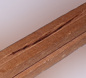 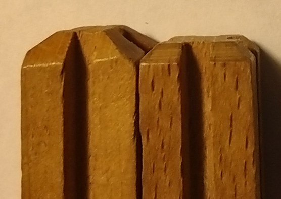 Burn mark from circular saw Left an older column with irregular tapering, right a later one Photo courtesy of Koos Welling Photo courtesy of Leen Kalden Base Plates Initially, base plates were made of 6 layers of uncolored cardboard glued together. The edges were cut vertically. Around 1932, the material was changed to tan-colored hardboard, and the edges were cut at an angle. After the war, the edges became almost vertical. In Jumbo sets, the hardboard was colored green instead of tan. 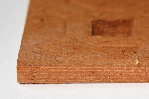
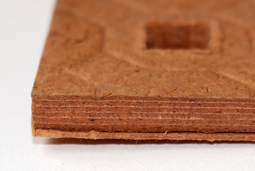
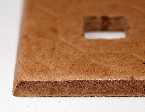 Layered cardboard Base Plate with vertical edges Same, with with extra layer to support columns Hardboard Base Plate with tapered edges From the start in 1924, the top of the base plates was embossed with an octagonal tile pattern centered on the holes. In probably 1926, both the top and the bottom of the plate were embossed. In probably 1927, the base plates got an extra support layer glued to the bottom so columns wouldn't fall through when moving the model, and only the top was embossed with a pattern (see above). This was done for one or maybe two years. Starting in probably 1928, the extra support layer was abandoned and embossing was on the top only. This continued until the end of production. Occasionally, more recent base plates are found with embossing on both sides, suggesting a production error. The octagonal pattern was used until approximately 1941, when it was changed to a circular pattern, which Jumbo maintained until the end of production in 1961. 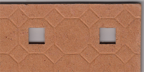 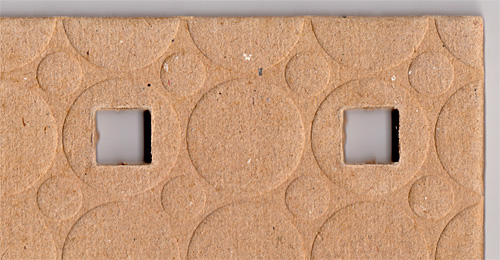 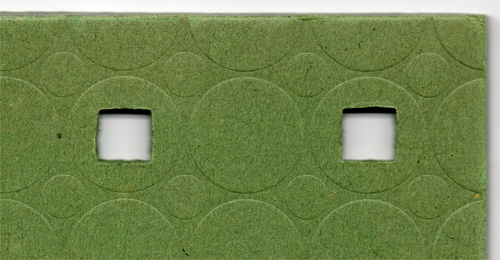 Tan cardboard base plate with octagonal pattern Tan hardboard base plate with circular pattern Green hardboard base plate with circular pattern (Jumbo) Parts stamping The 1931 N&T article has a picture (below left) of parts being stamped in a sheet metal press. Stamping was done with a punch (top part) and counter-punch (bottom part). The hardened cardboard was first cut into strips, probably using a metal shear press, and inserted into a feeder slot in the counter-punch. The operator then hit a foot switch which brought down the punch with great force, punching out the part which fell into a bin below or next to the machine. The cardboard strip was then moved a couple of inches and the process repeated. In this picture the operator is supposedly making Part #182 (peaked gable wall panel, 2 bays wide). But he is really just posing for the picture as the punch isn't properly attached to the ram, and the cardboard strip is not going through the feeder slot in the counter-punch! On the right a detail of the punch and counter-punch for roof panels #109 and #110. The teeth were punched out in a separate operation. 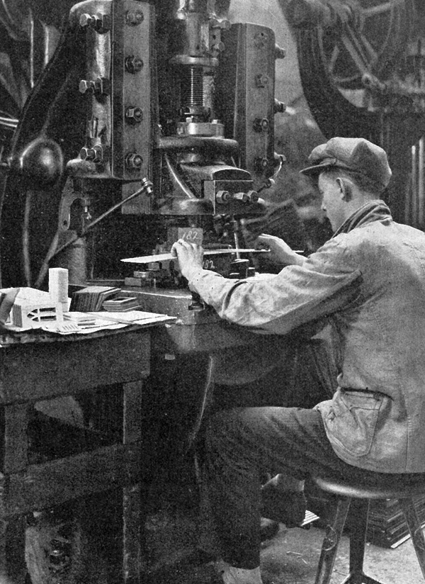
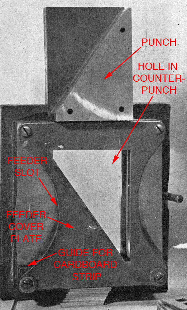 Scans courtesy Alex Geelhoed The article also shows the punch and counter-punch for square window part #20. Interestingly, the punch has two parts to it. Here how it works: a cardboard strip is fed into the feeder slot of the counter-punch, behind the cover plate. First, it is inserted ± 2 inches, upon which only the window openings are punched out. The cardboard strip is then moved ± 2 inches. The entire window is now cut out by the second part of the punch, while at the same time the openings for the next window are punched out by the first part of the punch. This way, every time the punch comes down, two operations (= 1 entire window) are executed simultaneously. Spacing indicates there was little waste. 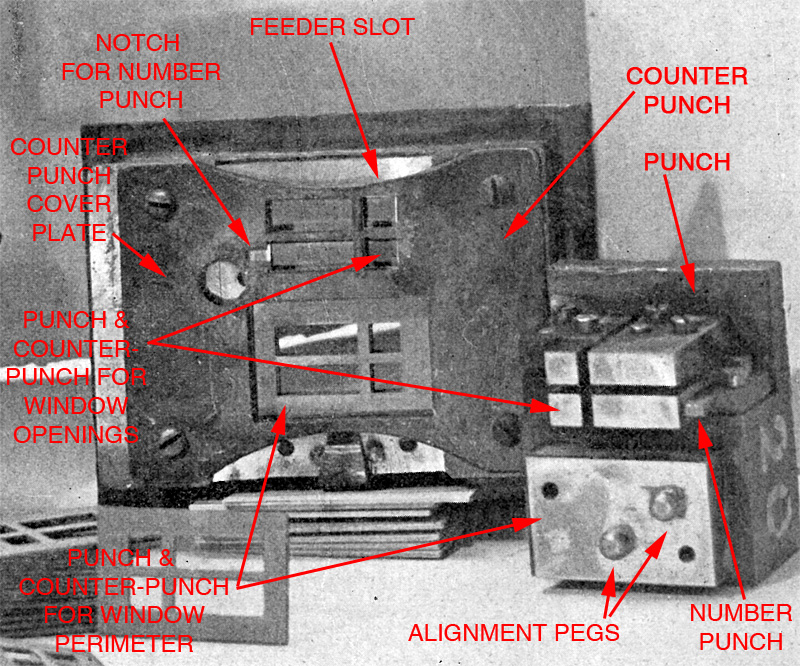 Scan courtesy of Alex Geelhoed Of special note are the alignment pegs. As the punch came down, the rounded pegs would push the window cut-outs slightly to the left or right before the entire window was punched out, ensuring the openings were properly centered. Still, alignment wasn't perfect, and there is slight variation in the width of the window frames. Also interesting is the number punch, visible next to the tall window opening on the punch. In the counter-punch, there is a corresponding notch. The number 20 was stamped into the cardboard at the same time as the window openings. Close observation shows that the number in the photo is placed sideways. This is how the number was oriented in the oldest windows with square openings (1931). Later, the number was turned 90 degrees so it was horizontal. The notch in the counter-punch was widened a bit to accommodate this and it appears it was widened to the left as the number isn't quite centered anymore. Still later, the typeface was changed to a more modern font, still slightly offset to the left: 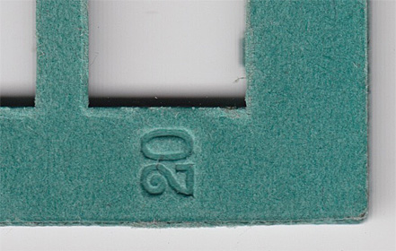 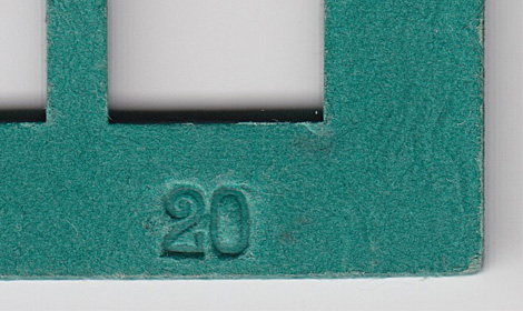 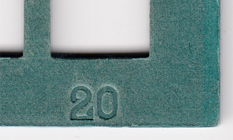 Version 1 of the window with square uppers Version 2 Version 3 Parts courtesy of Nick Cranendonk Parts numbering The placement and typeface of the numbers varied quite a bit. Initially, the numbers had serifs, but later became sans-serif. On some parts the number was always located on the same place, as it was imprinted while the part was being punched, as shown for window #20 above. But on most parts, the location and angle of the number seems fairly arbitrary, indicating that numbers were imprinted after the part had been made. Initially columns were numbered, but starting in 1927 columns were no longer numbered and you had to figure out yourself which column to use based on the illustration in the manual. Parts 60 and 62 weren't numbered until approximately 1931. Typefaces and number placement varied a lot and still being studied in more detail. Box construction and manufacturing During the war, boxes were stamped ZHC-P, referring to the Zuid-Hollandse Cartonnagefabriek (South Holland Cardboard Factory) in Delft. There is one example of such a box that uses pre-war paper, which suggests that ZHC may have been the box manufacturer before the war, and perhaps even from the beginning in 1924. Preliminary findings suggest this may have been the case, and this is being further researched. The boxes always consisted of two parts, a bottom and a lid. There were no dividers inside the box (although there were dividers in the post-war Jumbo boxes). Construction of the boxes changed over time, helping to date the sets. The boxes were made with gray cardboard, over which embossed colored paper was glued. The paper was wrapped around the side flaps and into the inside. The corners were then stapled. Initially the inside of the lids were not lined, you could see the gray cardboard. But starting in 1927 (31xxx series Set 0 and 51xxx series Set 00), white paper was glued to the inside of the lids, leaving a few mm of the colored paper exposed and hiding the inside part of the corner staples. The outside corners were then reinforced with metal corners brackets which covered the outside of the corner staples. The sides of the box bottoms were wrapped with the same embossed colored paper as the lid, and it also wrapped around to the inside. The insides of the bottom boxes were never lined, you could see the unfinished cardboard. The underside of the boxes was covered with different type of paper than the lid, without embossing, probably because the embossing was rather fragile and would wear off fast. Box paper The embossing on the paper was subtle, and gave the sets a distinctive look. So far, I haven't been able to find the manufacturer of the paper. Initially, the paper was a bit dull, but starting in 1931, it had interesting reflections. Here the chronology of the paper types. Images are enlarged to show detail: Paper on the lid, and on the sides of the bottom box: 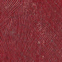
 
 Fan pattern Network pattern Wave pattern Leaf vein pattern Sand paper pattern In Dutch: Waaier structuur Netwerk structuur Golfjes structuur Bladnerf structuur Schuurpapier structuur 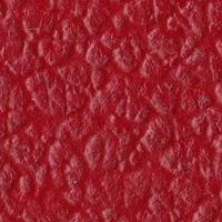
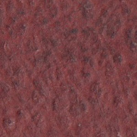
 All sets courtesy of Nick Cranendonk All sets courtesy of Nick CranendonkLeather pattern Printed spot color In Dutch: Leer structuur Gedrukte steunkleur (Set/Doos 000 & 00) Paper at the bottom of the boxes: 


 Burgundy Orange Brown ostrich skin pattern Brown fine pattern Orange wood grain pattern In Dutch: Bordeaux rood Oranje Bruine struisvogelhuid Bruin met fijne textuur Oranje houtnerf 
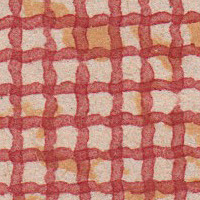

 Red giraffe pattern Red mesh pattern Striped white cardboard White cardboard In Dutch: Rood girafpatroon Rood gaaspatroon Gestreept wit carton Wit carton (Set/Doos 000) (Set/Doos 000 & 00) Chronology of lid and bottom papers: Set 000 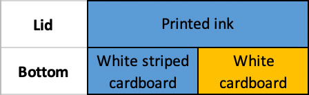 Set 00  Set 0  [Other sets still under investigation] Corner reinforcements Initially, boxes had narrow galvanized (gray) reinforcements at the corners, with small holes. These tended to come off fairly easily and starting in 1927 they switched to wider reinforcements with larger holes. Even so, the attachment isn't very durable, and many boxes found today have torn corners without reinforcements. During the war, only the lids were reinforced and bottom boxes were simply papered over at the corners. The brackets were painted silver instead of galvanized and tend to rust. After the war, the corner brackets had an extra row of holes at the fold line and were painted black, light gray or brown. Economy Set 000, introduced in 1932, initially had wide brackets, but in the late 1930's it had narrow brackets. During the war, the bottom box had a flat staple instead of a bracket, and after the war Here the various types: 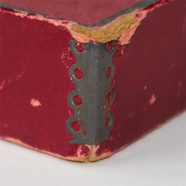 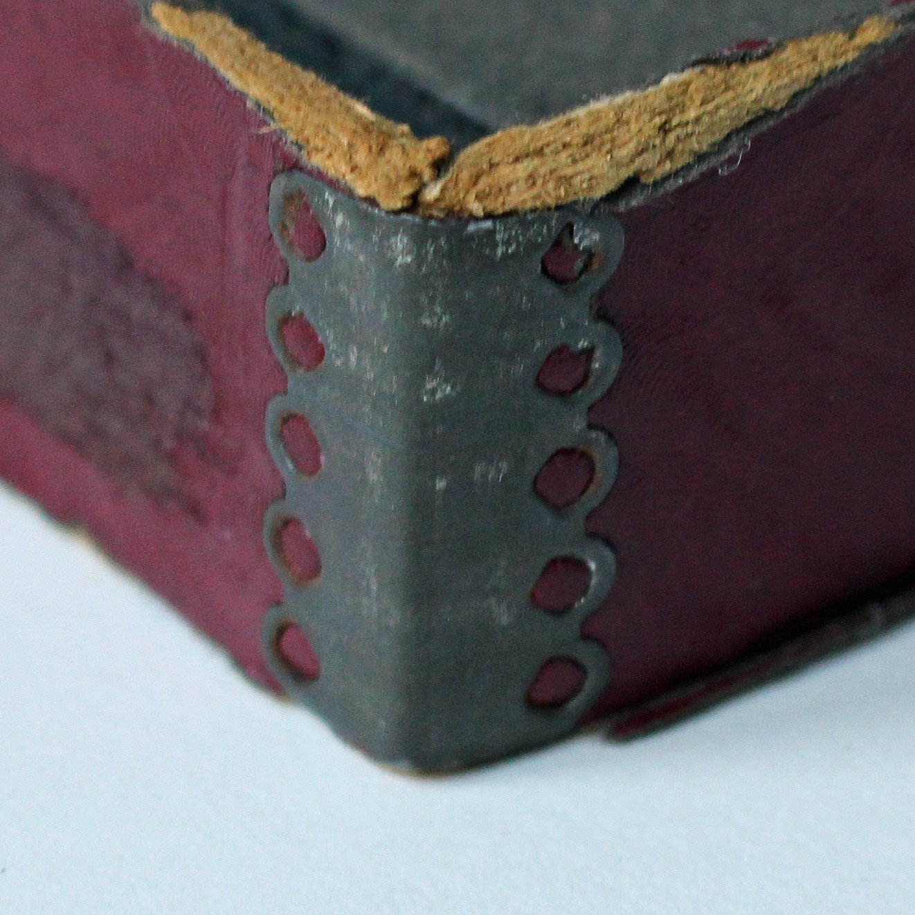
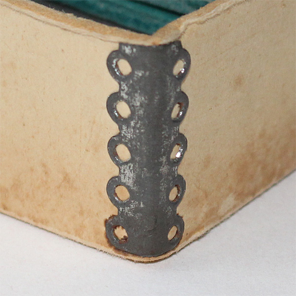 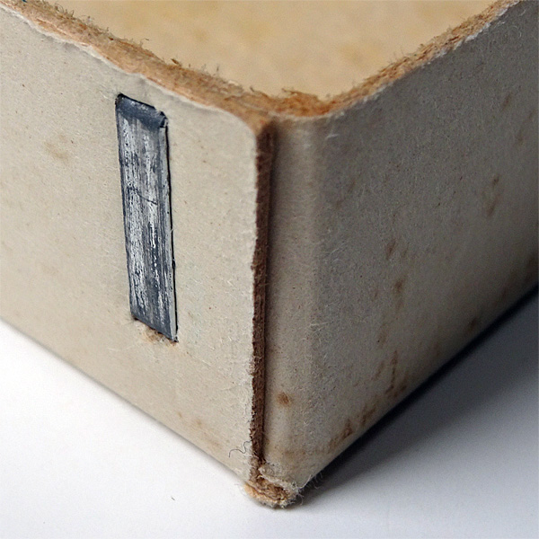
Narrow galvanized brackets Wider galvanized brackets Narrow galvanized brackets Galvanized flat staple at on oldest sets starting in 1927 on economy sets 000 & 00 bottom box of war Set 000 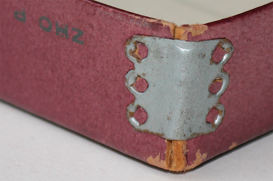 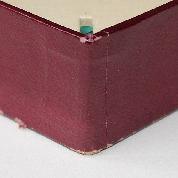
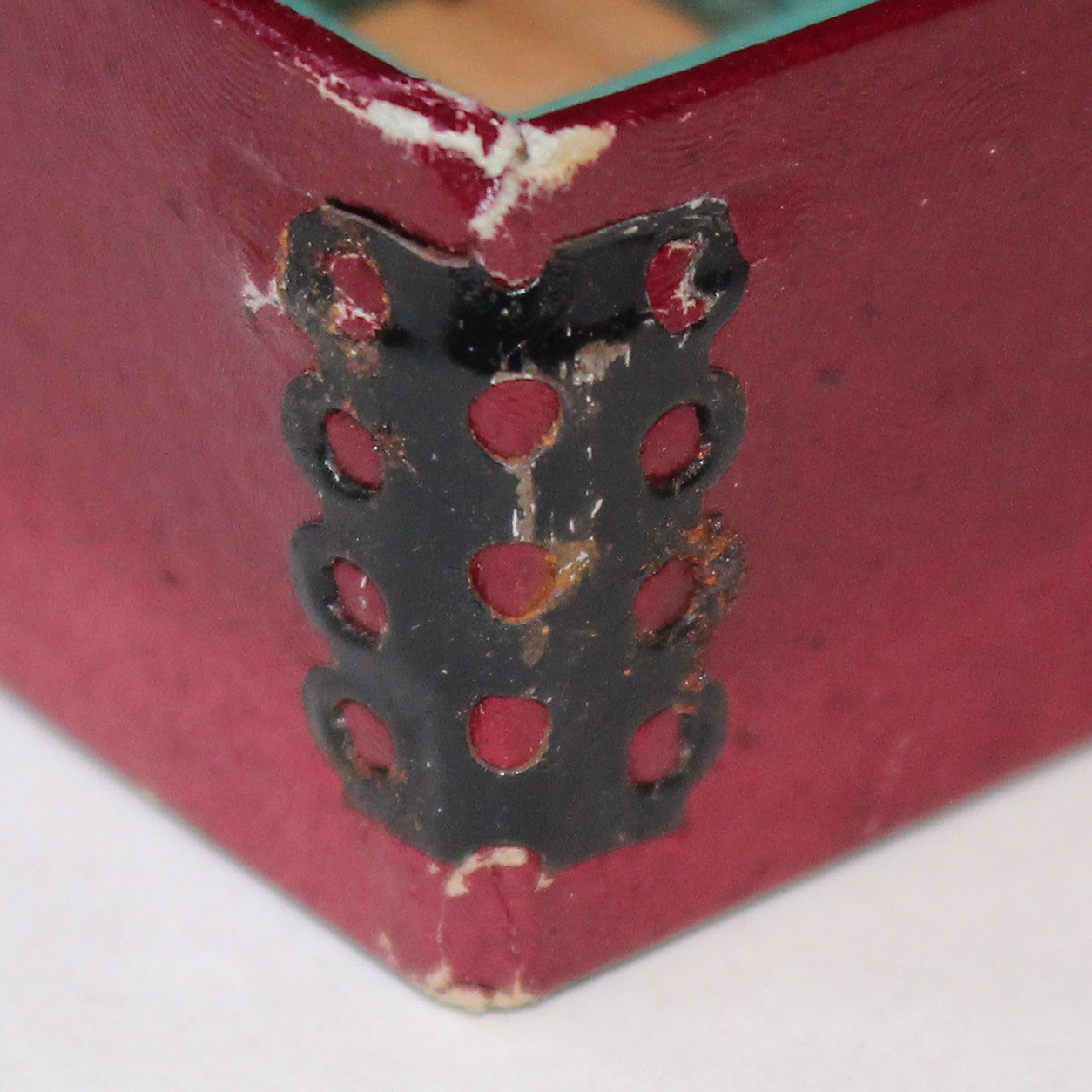 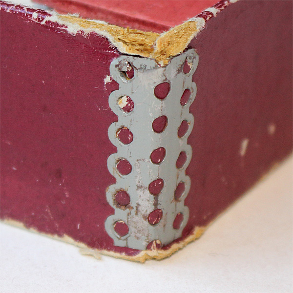 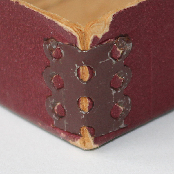 War sets (recognizable by the ZHC P mark The bottom box of war Post-war bracket with holes Post-war bracket with holes Post-war bracket with holes on the lid flap) had silver painted brackets sets had no brackets at corner, painted black at corner, painted light gray at corner, painted brown Sets courtesy of Nick Cranendonk Production schedule Nothing is known about the production schedule. Rumor has it that "Moubal cleaned there machines once a year to produce Mobaco" and that it took about a month. Some Mobaco friends and I put together this speculative schedule, working back from delivery to toy stores for Sinterklaas, the Dutch version of Santa Claus. Sinterklaas comes on steam ship from Spain, and on the night of 5 to 6 December, he rides over the roofs on his white mare and drops presents through the chimney for children who behaved well during the year! The Sinterklaas and Christmas sales season started mid November, so Mobaco sets had to be in toy stores by then. • End of January: Sinterklaas and Christmas sales are reviewed with Distributor(s) and stores; changes to sets and to artwork are discussed and where necessary new artwork is commissioned. • Through the end of May: toy stores send in their orders to the Distributor. Through 1931 that was Bosch Honig in Utrecht, after that perhaps it was Moubal itself. • Beginning of June: production planning (2 weeks) • Mid June: cardboard, wood and boxes are ordered (8-week lead time); artwork for the picture on the lid and for the set contents are sent to the printer; printer starts production (4 weeks including print checks). This is corroborated by the printer code on some of the set contents which indicate a July printing date. • Mid July: printed images are sent to the box manufacturer, who starts production (4 weeks); art work for instruction manuals and price lists are sent to printer, who starts production (4 weeks incl. print checks) • Mid August: cardboard material, wood, instruction manuals, price lists and empty boxes are delivered to Moubal; 4 week buffer period until start of production • Mid September: machines are cleaned and production of cardboard and wood parts commences • Beginning of October: boxes are filled while parts production continues. • Mid October: completed boxes are delivered to Distributor • Mid October through early November: Distributor assembles delivery packages for each store and delivers them in time for the Sinterklaas sales season Good boys (and a few girls) would find a Mobaco set next to the fireplace in the morning of December 6th, and immediately start building! |
||||||||||||||||||||||||||||||||||||||||||||||||||||||||||||||||||||||||||