| INTRO | PARTS |
SETS Moubal Jumbo |
MANUALS Moubal Jumbo |
MARKETING |
PRICE
LISTS |
BUILDING |
MOUBAL RELATED |
BUILDING A MOBACO MODEL |
||||||
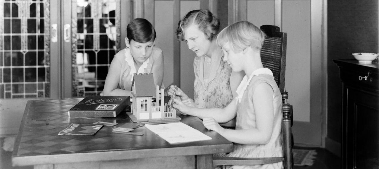 Image courtesy
Nationaal Archief.
1931 photograph by Willem van de Poll of his wife Nell Langlais and her daughters Hans (left) and Renée playing with Mobaco (cropped). Shown is a 1931 Set 0 with square
windows and the new box design with a cursive
logo. A price list
with a Job de Nijs illustration lies folded on the
table.
A gnomes 00-0-1 Manual lies on the table, recognizable by the larger perspectives than used in the earlier instruction manuals. The manual is opened to designs 5 and 6, and design 6 is being built. This shows that in 1931, the gnomes manuals were in use. Hardly visible behind the house lies the small instruction leaflet. In a Natuur & Techniek article, also from 1931, we see this set being packed with Art Deco manuals (and the instruction leaflets). So in 1931, they produced sets with the Art Deco manual and sets with the gnomes manual. The Art Deco manuals were probably leftover stock. This indicates that the gnomes manuals were introduced in 1931, the same year the gnomes brochure is mentioned in a trade fair article. |
||||||
|
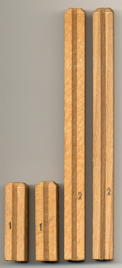
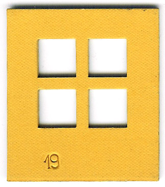
STEP BY STEP INSTRUCTIONS Construction of Model #48 is illustrated here. It's really easy! 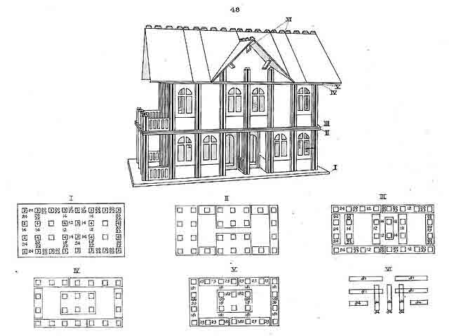 The instructions are very efficient - the entire model is explained on just one page! The roman numerals of the floor Diagrams are keyed on the perspective. Step 1 - Getting Started 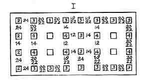 Diagram I shows which ground plate to use (the one with 4 x 8 holes). If you ever plan to move the model, set the ground plate on a tray or so. The columns tend to drop through the holes when you lift up the ground plate. 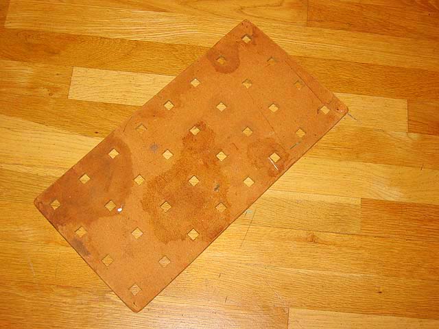 Step 2 - Setting the columns
Diagram I also tells you which columns to put where: small numbers inside the squares indicate the length of the columns (2, 3 or 4). 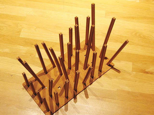 Step 3 - Inserting wall panels
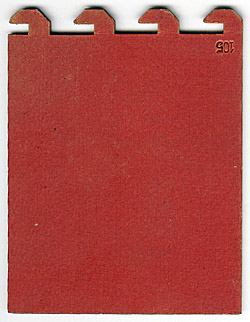
Diagram I also tells you which wall panels to insert: use the part number indicated between the squares. Each cardboard items is imprinted with a part number, which makes it really easy. Sometimes you must stack two parts. First insert the bottom number (often part #22). 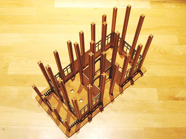 The columns are now pretty straight, although a little wiggly at the corners and in long walls. But that's taken care of in the next steps. Step 4 - Adding top plates and floor plates 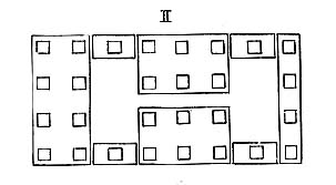 To give the model rigidity, and to create floors, top plates and floor plates are inserted over the columns. Diagram II shows which plates go where. As you can see, the diagram is not quite to scale. In reality, the narrow strips aren't as wide. 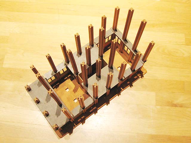 Step 5 - Second layer of top plates and floor plates 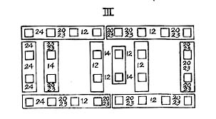 Diagram III shows which plates go where. 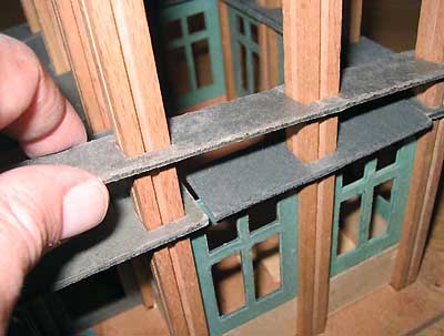 Why a second layer of top plates? As you can see in the photo, there are gaps between the top plates, which are weak points in the structure. Especially at the corners. Adding a second layer of plates that bridge over the gaps takes care of that. By the way, this system is the same as used in traditional wood frame construction: walls always have a double top plate, with the joints staggered for strength. 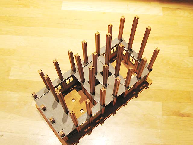 In order for the next layer of wall panels to be level, there must be two layers of plates where wall panels are added on top. Step 6 - Second story wall panels Diagram III also shows which wall panels to insert where. Again, the lower number is the one to install first, in many cases Part 23. 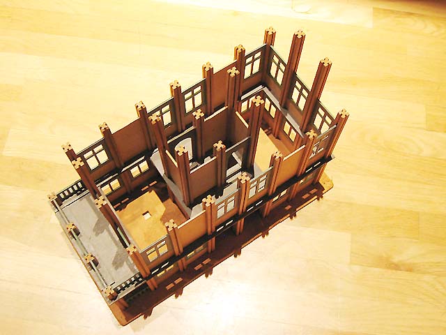 Steps 7 and 8 - Second story top plates/floor plates (two layers) 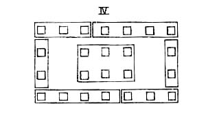 Diagrams IV and V show how to install the two layers of top plates/floor plates. The model is now really sturdy. 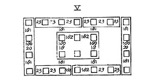 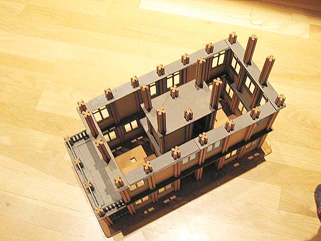 Step 9 - Third floor wall panels Diagram V also shows which wall panels to install. Step 10 - Roof rafters 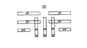 Diagram VI indicates which roof rafters to use. Unfortunately, some parts were missing in my set, so my model does not have the side dormer... 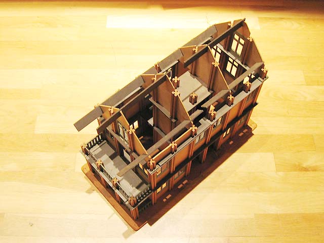 Step 11 - Install Roof 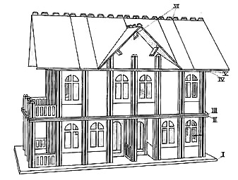 There is no diagram for the roof panels. You have to look at the perspective drawing. The roof panels have "teeth" at the ridge so they can interlock. The roof panels are not attached, but kept in place by gravity. 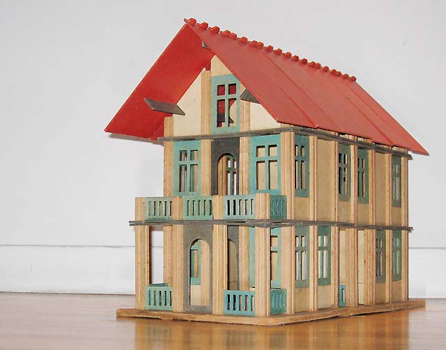 The finished house stands over a foot tall. Notice that the upper openings in the windows are square, while the drawing shows arches. For a while, Mobaco shipped old manuals with the new windows. Later, they fixed some of the manuals. The square openings look more "modern". Interestingly, the doors are still arched! Step 12 - Dismantling All good things come to an end... But taking the model apart is really easy! It only takes a couple of minutes. Try that with a Meccano, Erector or even with a Lego model of this size! Once you build a few models from the instructions and get the hang of it, it's fun to design your own! Or you can try your hand at a Set 5 model: 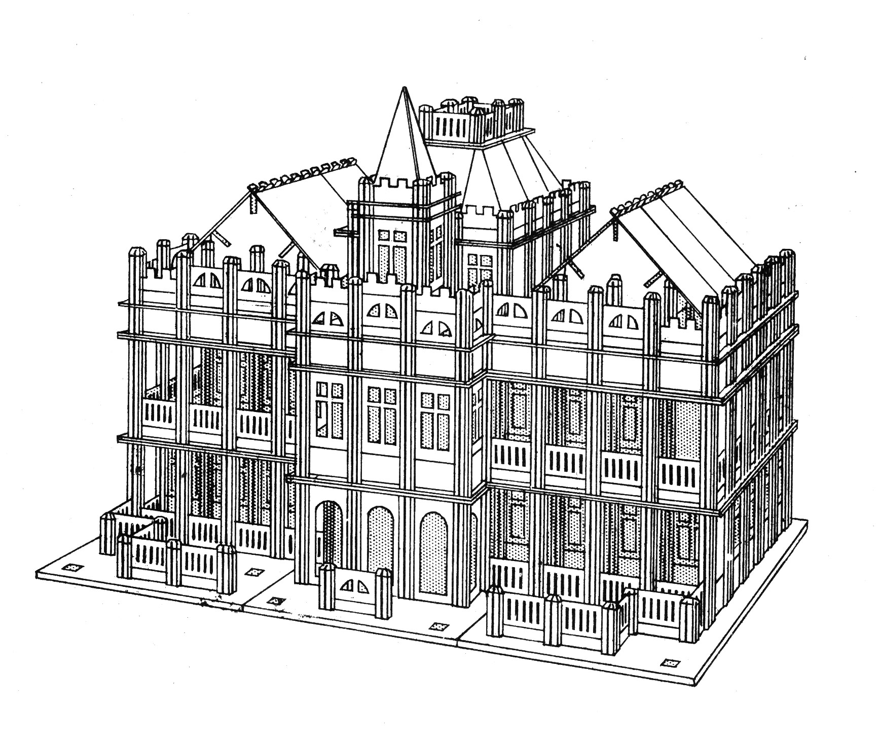 |
|||||
MOBACO MODELS
Here a smattering om Mobaco models
built by various (adult) Mobaco builders.
|
||||||
This massive 1:100 scale Mobaco model of the Sagrada Familia was made by by Giliam de Valk in The Netherlands. Where necessary, Giliam made his own columns from standard 12 x 12 mm wood dowels and cut the grooves with a table saw. He also made custom cardboard parts with museum board, such as in the steeple or the tall spires, all in keeping with the spirit of Mobaco. Needless to say, a lot of planning goes into the making of such a model! 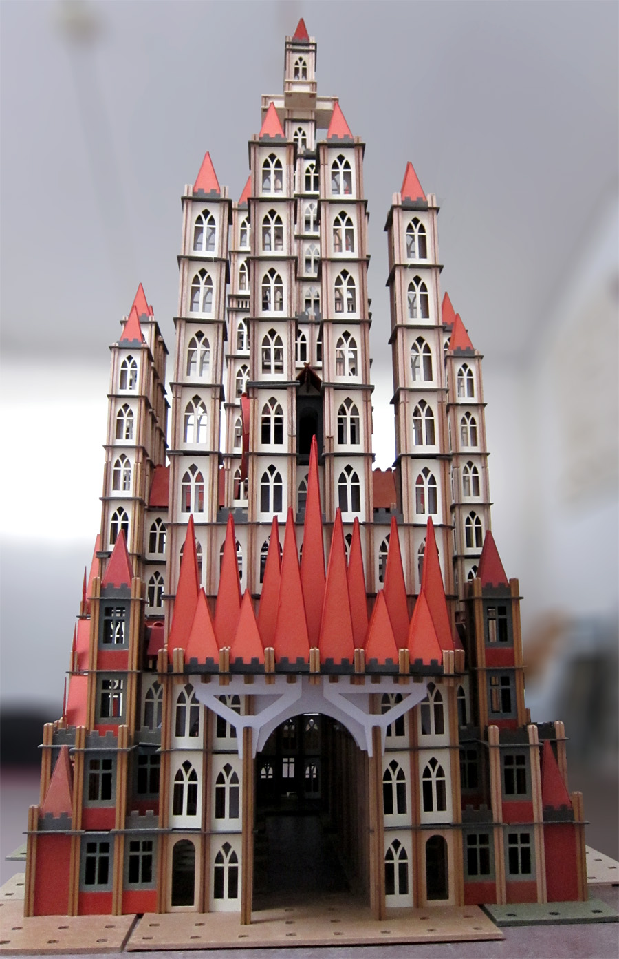 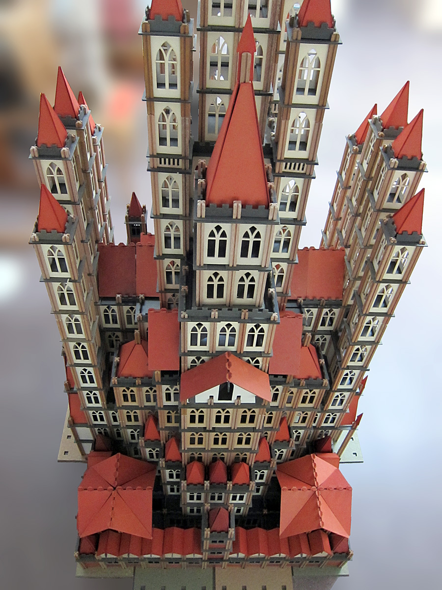 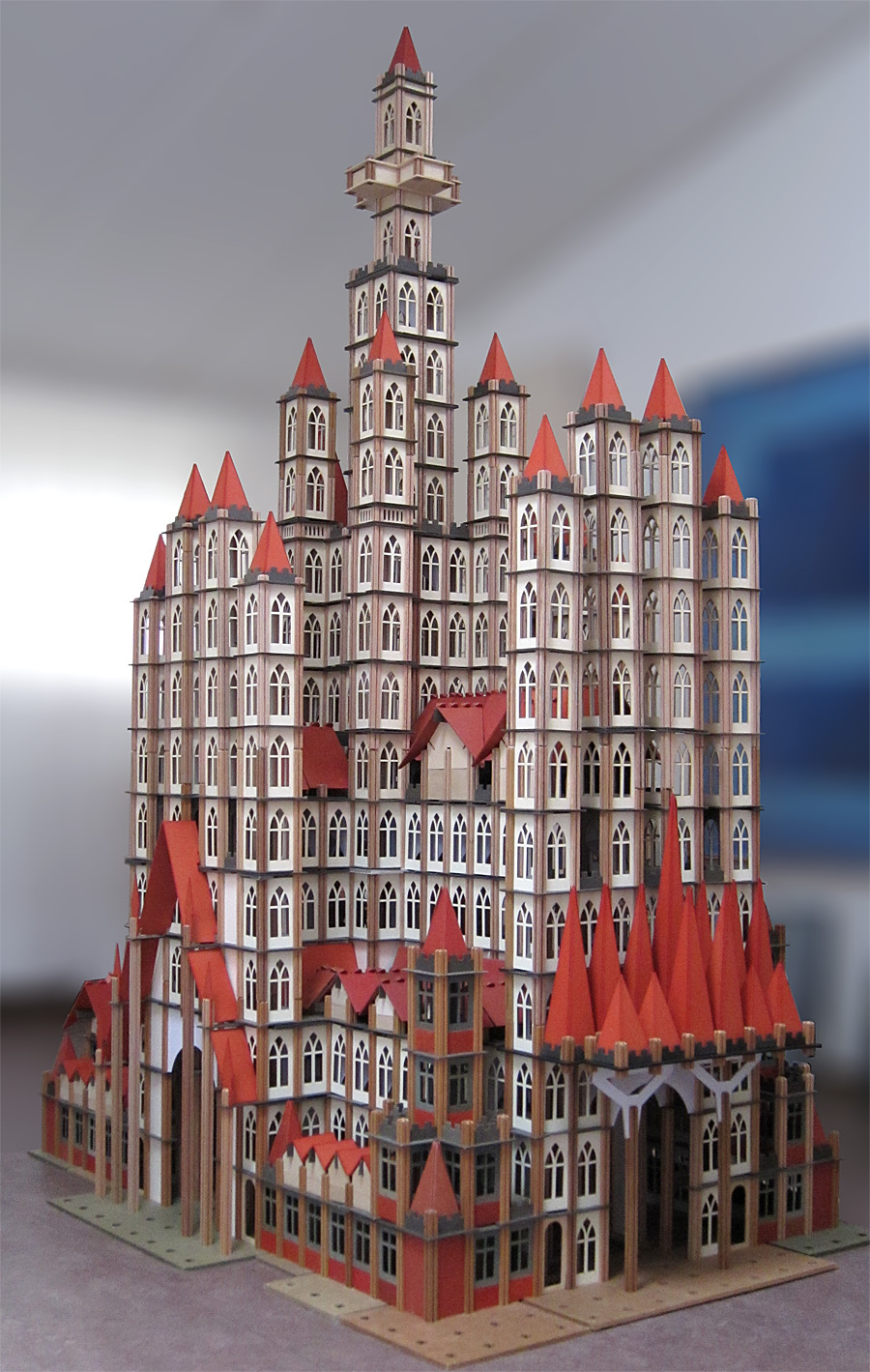 Sagrada Familia under construction, with the custom spires before being painted to match the Mobaco roofs: 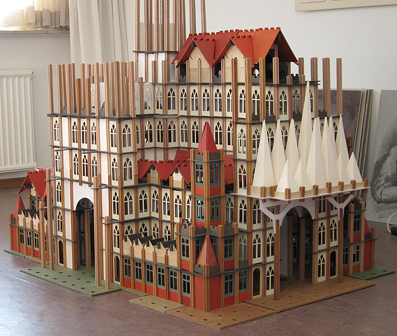 Sagrada Familia under construction, interior view: 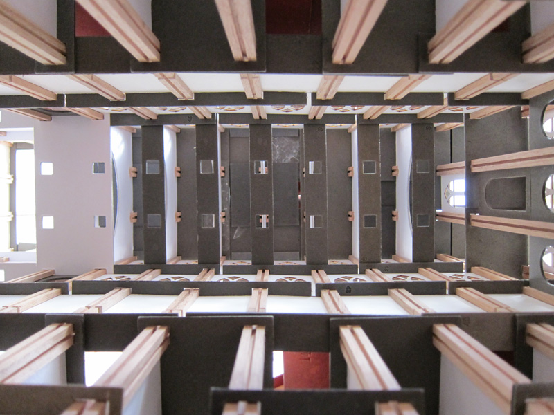 All photograph's courtesy of Giliam de Valk This lovely building by Nick Cranendonk is model no. 75 from Set 4, as shown in the Gnomes Manual: 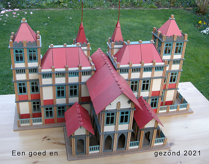 Photo courtesy of Nick Cranendonk Also by Nick Cranendock are these buildings made with pre-1931 parts, which had muted colors and featured round windows. Clockwise from bottom left: Train Station 1 (platform roof and station house), Set 1 building #18, Set 2 building #33, Train Station 2 (station house and platform roof). 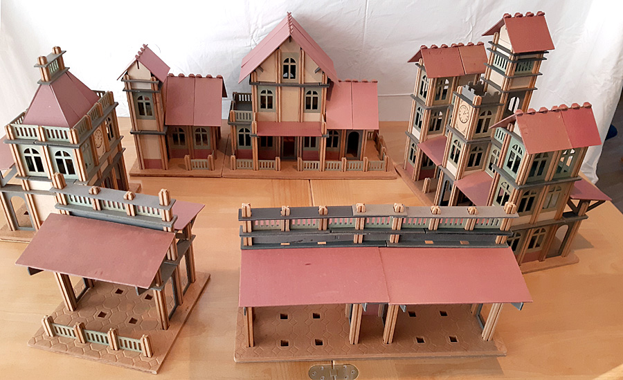 Photo courtesy of Nick Cranendonk A whimsical Giliam de Valk model of homes along an Amsterdam Canal: 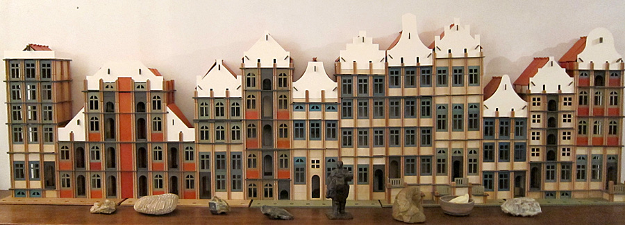 Photo courtesy of Giliam de Valk This inspired builder Gerard Poort to make his own interpretation of an Amsterdam Canal: 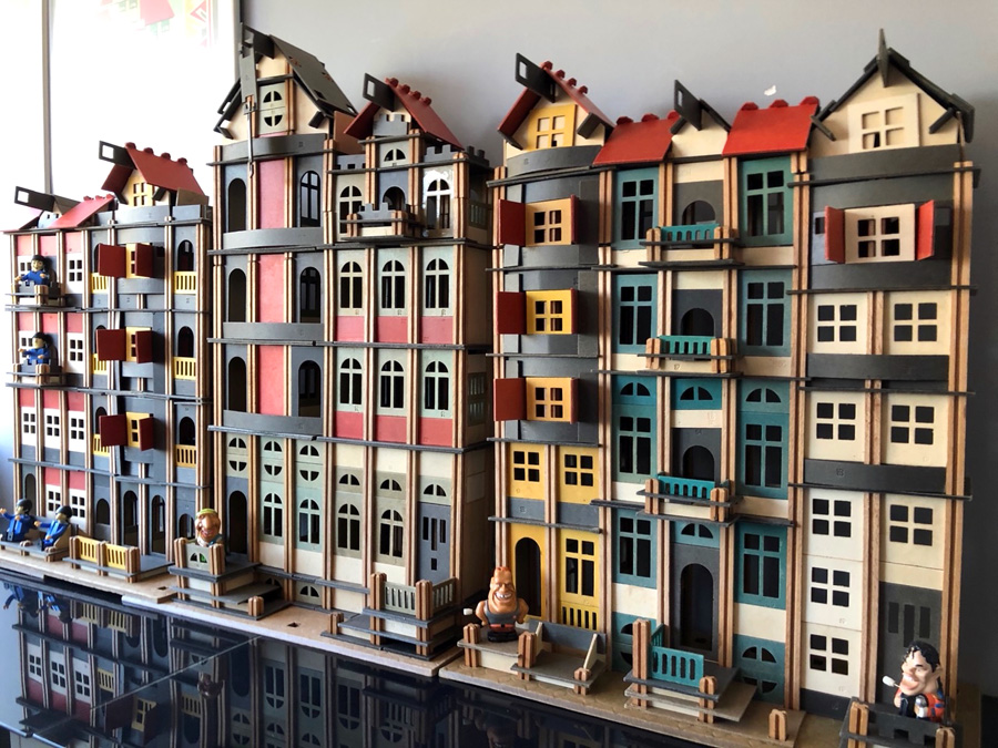 Including some creative use of Mobaco to create boats and a car: 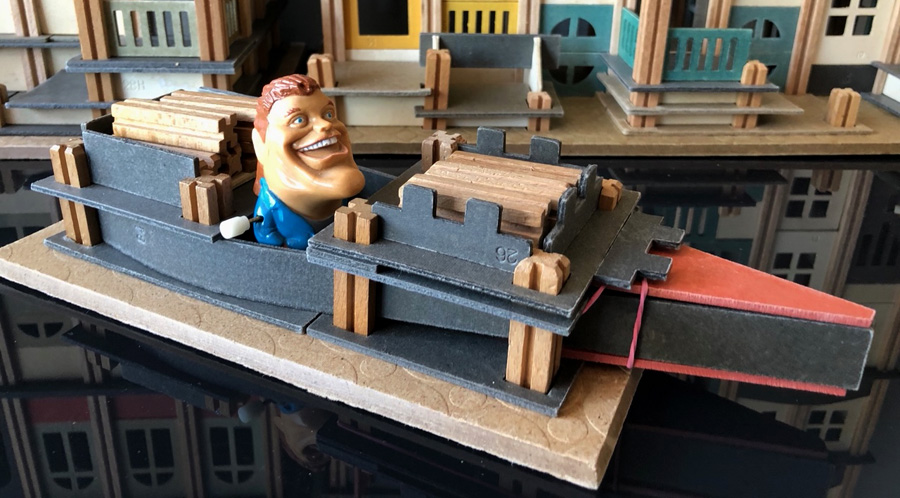 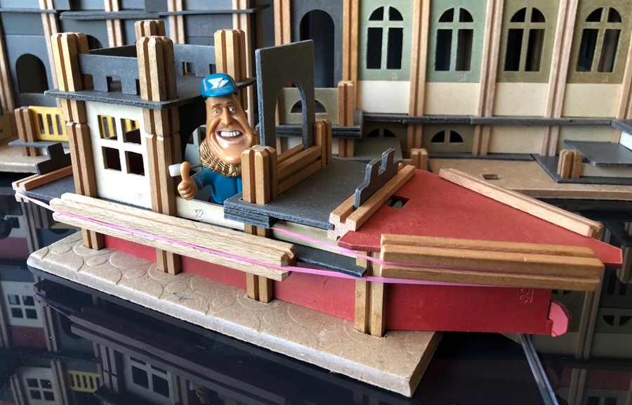 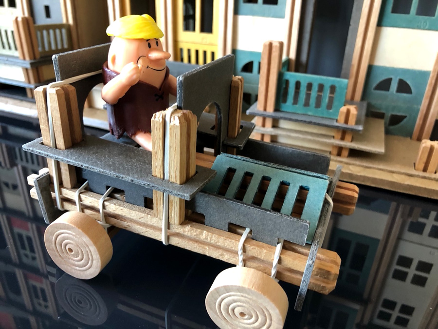 Photo's courtesy of Gerard Poort Seven year old Adam Bollod was inspired by his grandfather to build this Dinosaur Museum! 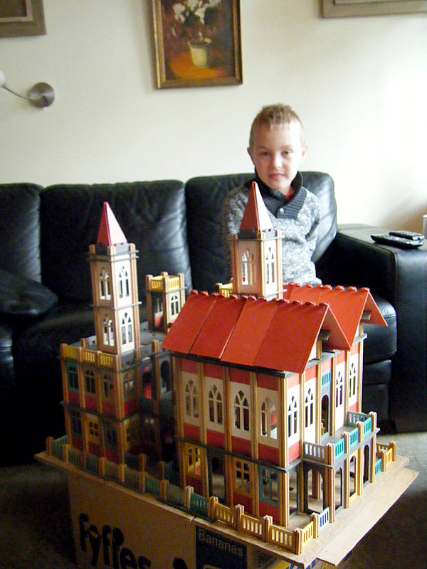 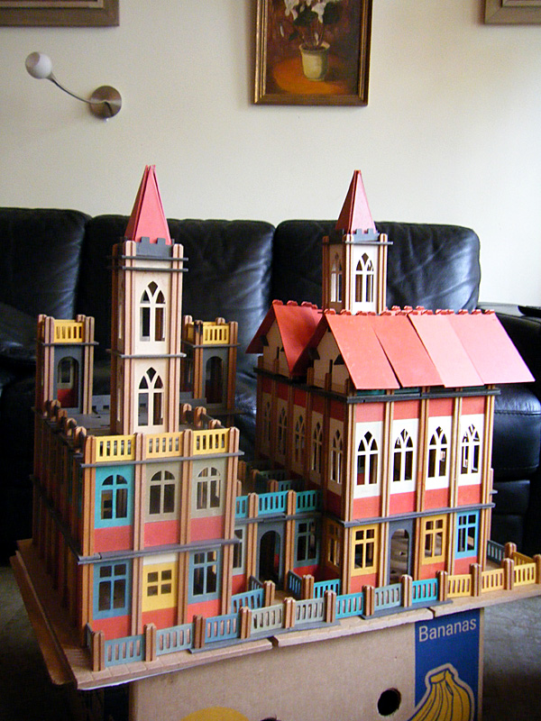 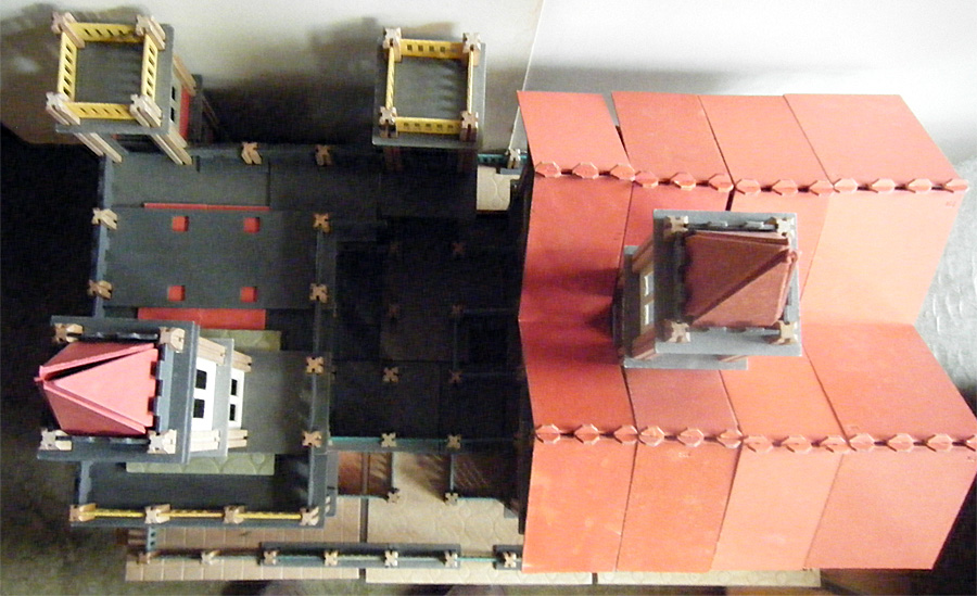 Photo's courtesy of Robj Schiff Gerard Poort built this doll house, complete with LED lighting: 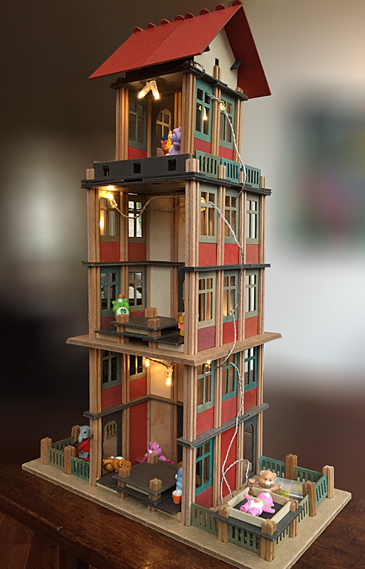 Photo courtesy of Gerard Poort Several advertisements in the early 1930's featured this undocumented model. Gerard Poort rebuilt it from that one view. He didn't have enough Gothic windows and white solid panels, so he had to improvise a bit! Note: the ad features window panels with narrow tall windows that never existed! Also, it shows an 8 x 8 hole ground plate which didn't exist either. 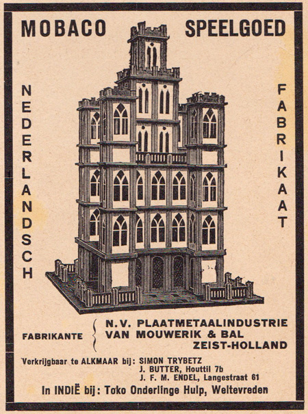 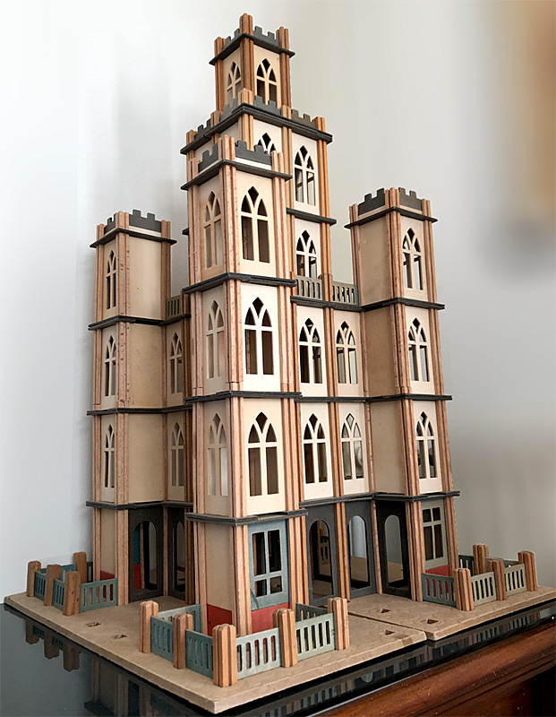 Advertisement courtesy of Leen Kalden. Photo courtesy of Gerard Poort Angled buildings are impossible in Mobaco. Gerard Poort found a way to build Jachthuis St. Hubertus, designed in 1914 by famous Dutch architect H.P. Berlage for Mr. and Mrs. Kröller-Muller, by angling the ground plates: 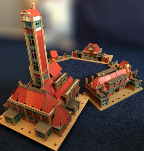 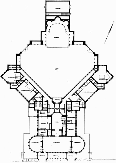 Photo courtesy of Gerard Poort. Floor Plan Creative Commons |
||||||
Max Horncy from
New Zealand built this Model #24 with
a pre-1931 Set 1 (round windows and muted roof panels
and windows):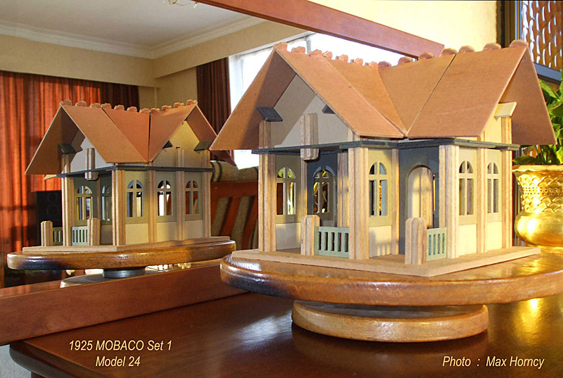 Photo courtesy of Max Horncy Mobaco models 69, 68 and 77, built by Robj Schiff, The Netherlands: 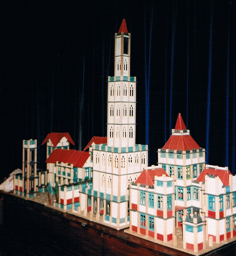 Photo courtesy of Robj Schiff Jumbo model, built by Johan Jager, The Netherlands: 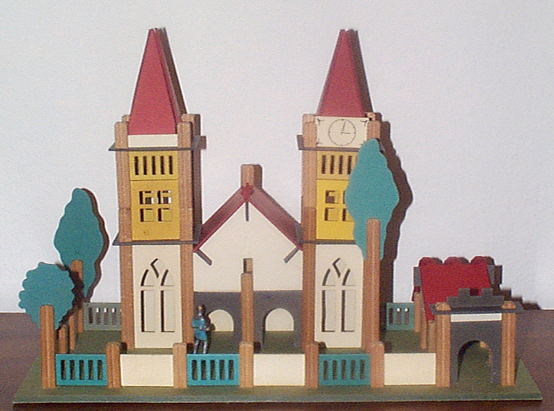 Photo courtesy of Johan Jager |
||||||